
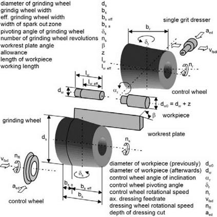
In centreless external cylindrical peripheral longitudinal grinding, there is a larger number of parameters, as can be seen in Fig. 6-56. The workpiece can sometimes have cranks of smaller diameters that are not to be ground and is characterised by the main dimensions and stock allowance z.
To reduce the workpiece stock allowance, the grinding gap must run conically in the feed direction. This can be achieved by shaping the grinding wheel with a conical roughing zone and cylindrical spark-out zone. One setting common in practice is also pivoting the control wheel by the angle 5r with a cylindrical grinding wheel. In this case, the empirical experience of the machine adjuster is especially important, as it is hardly calculable by inexact tool alignments. Further practices, like angling the grinding wheel or workrest plate, have a similar effect on achieving grinding cap conicity.
The workpiece feed is created by inclining the control wheel in relation to the axis-parallel arrangement of grinding wheel and workpiece by the control wheel inclination angle ar (Fig. 6-57). The control wheel peripheral velocity vr is transferred to the component as feed or throughfeed rate vfa and workpiece speed vw.
If there is no slipping between the workpiece and the control wheel, the feed rate is calculated as follows
|
Fig. 6-37. Geometrical and kinematic variables in centerless longitudinal grinding |
|
|
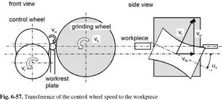
When slipping between the workpiece and control wheel is ignored, the workpiece peripheral speed is calculated as follows
vw = vr cos ar. (6.88)
The inclination of the control wheel necessitates a hyperbolic shaping. If the control wheel were cylindrical, it would only make contact with the workpiece at one point. The hyperbolic shape of the control wheel guarantees on the other hand a linear contact with the lineally moved workpiece. This profile is created by means of a single-grain dresser, which is manually pivoted or can cut the hyperboloid form by NC control.
The control wheel can have a conical or symmetrical shape (Fig. 6-58).
conic hyperboloid symmetric hyperboloid
|
|
|
Fig. 6-58. A hyperboloid control wheel [MEIS80] |
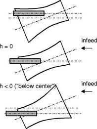
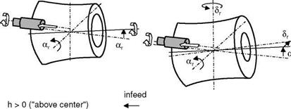
For grinding machines with manual dressing settings or dressing templates, the parameters of dressing inclination angle adr in relation to the horizontal and dressing altitude hdr in relation to the control wheel centre are adjusted.
The angles are calculated as follows:
The symmetrical hyperboloid is only dressed below the dressing angle adr with a dressing altitude hdr = 0. After shaping, the control wheel is pivoted under the angles a’r and 5 r[MEIS80]:
This method has the advantage above all of minimal dressing amounts on the control wheel.
 |
|
Workpiece diameter reduction results in centreless throughfeed grinding from the feed rate vfa in conjunction with the grinding gap setting. The actual material removal rate be calculated by means of equation 6.93, whereby one should take into consideration that the total workpiece length lw can be different from the ground workpiece length lw eff.
The specific material removal rate Q’w can only be calculated for centreless grinding knowing the exact grinding wheel width bs eff.
n most applications however, the effective grinding wheel width is unknown and changes with wear, which is why the specific material removal rate parameter Q’w is hardly prevalent in centreless throughfeed grinding technology.
Towards the runout, the grinding gap should be set parallel so that grinding can proceed without or with minimal depth of cut. By means of this measure, comparable to spark-out, the surface quality improves and, with suitable grinding gap settings, no feed marks show up on the workpiece from the grinding wheel edges on the runout side.
During throughfeed grinding, workpiece supply and removal is very important. For this purpose, grinding machines have adjustable guide bars, whose optimal setting requires craft and ability on the part of the machine operator. The component entry must be shaped linear to the control wheel, since otherwise errors will be ground into the component that destabilise the process or can no longer be removed during the rest of the process. On the exit side, the workpieces must be guided with an even higher parallelism, since the grinding wheel edge will otherwise grind shape errors and feed marks into the finished workpiece surface.
The removal of the workpiece stock allowance has to be distributed across the grinding wheel width in a way which does justice to the process at hand. Nonetheless, wear, characteristic of centreless grinding processes, will form along the grinding wheel axis, also known as the “centreless-hole”. This wear develops whether or not the grinding wheel conicity is produced by a corresponding shaping of the grinding wheel or by pivoting the control wheel [KOEN84].
In accordance with the axial feed per workpiece revolution fa, the grinding wheel can be subdivided into sections parallel to the axis. In the grinding zone, every region of width fa must remove one part of the workpiece stock allowance. If one grinding zone section wears off, part of the stock allowance z of the workpiece material that went unprocessed becomes the responsibility of the following section. Grinding wheel wear in the grinding zone increases in the feed direction, since every grinding zone section has to compensate for the wear of the previous section. In the spark-out zone, the wear drops again, which is why the centreless — hole forms characteristically between the grinding zone and the spark-out zone.
Stable process design is influenced by the same mechanisms as in plunge grinding, however it takes on more complexity because of the third dimension of the grinding gap in the feed direction. Geometrical stability, for example, must be calculated iteratively along the component feed direction. The overlap ratio U should be considered as it is decisive for the formationreduction of roundness errors in the spark-out zone. However, roundness errors with a high amplitude enter-
 |
ing in the roughing zone can be so dominant that they can no longer be removed in the spark-out zone.