
 To evaluate the machining process, the development of process forces was analyzed for a path — controlled feed speed. Figure 20.14 illustrates that a grinding operation without ultrasonic assistance
![]()
|
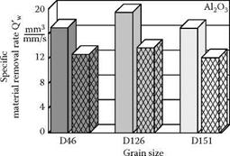
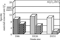
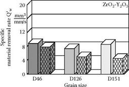
FIGURE 20.12 Material removal rates during conventional and ultrasonic-assisted grinding of ceramics in relation to the grain size of the tool.
produces a poorer process because rapidly increasing axial forces occur. After a grinding time of tc = 22 s, the force already reached a value of Fz = 240 N. This level could no longer be tolerated, so the process had to be stopped. A permanent wheel-workpiece contact is responsible for faster blunting of the grinding coating, leading to a strongly reduced cutting ability. This results in an
Ultrasonic-assisted cross-peripheral grinding
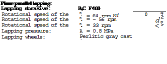
Grinding tool: D46 ST50 C90
Cooling lubricant: solution 4 %
Amplitude: Лш = 12 pm
Cutting speed: v* = 5.7 m/s
Depth ofengagement: ap = 0.5 mm Working engagement: ae = 15.6 mm Feed speed: vfr = 30 mm/min
 |
 |
![]()

![]() Material removalrate: Qw = 3.9 mm3/s
Material removalrate: Qw = 3.9 mm3/s
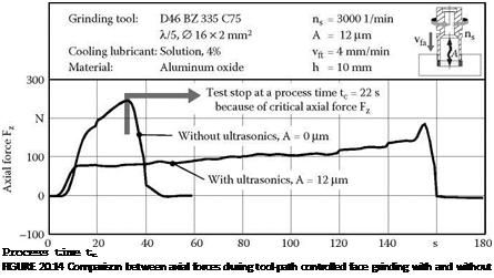 |
enormous increase in force if feed speeds are constant. Therefore, economic production of such contours with conventional methods (grinding without ultrasonics) is not possible.
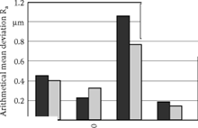
Figure 20.15 shows the influence of ultrasonic oscillations on the process forces during face grinding. The height of the surface-related axial forces depends on the machined material. Alongside fracture toughness, stability and hardness of the material play an important role here.
While the highest surface-related material removal rates of Q w = 25 mm3/mm2/min are achieved for aluminum oxide, they decrease to Q w= 5 mm3/mm2/min during the machining of silicon nitride. A maximum surface-related axial force of 6 N/mm2 was chosen as a critical value. It can be observed in the case of zirconium oxide how the process forces behave in contrast to conventional face grinding. There are similar surface-related axial forces at Q w= 2.5 mm3/mm2/min during conventional
and at Q’w = 15 mm3/mm2/min for ultrasonic-assisted grinding with AUS = 14 pm. This is a sixfold increase of the material-removal rate.
Ultrasonic-assisted grinding is a novel finishing process for economic machining of brittle-hard materials. The superposition of the kinematics of the grinding process with ultrasonic oscillations leads to removal and wear mechanisms different from those during conventional grinding. There is microsplitting due to the high stress of the abrasive grains, provoking the constant formation of new sharp edges. The processes are characterized by small process forces with a quasistationary process during the machining allowing an increase of the material-removal rates.
In peripheral grinding with radial ultrasonic superposition, a reduction of process forces of up to 90% could be observed in contrast to conventional grinding with the same specific material — removal rate. At the same time, wear of the grinding wheel as well as surface quality of the machined workpieces increase slightly. In peripheral longitudinal grinding with axial superposition, structured surfaces could be formed and directional machining marks avoided with the help of the kinematics.
In cross-peripheral grinding with axial ultrasonic excitation, complex contours with high specific material-removal rates can be achieved despite the low cutting velocities. At the same time, high surface qualities and shape accuracies can be realized.
In the future, process behavior has to be improved through the definition of harmonized optimum parameters for the ultrasonic oscillation and for the grinding process. Furthermore, wheels have to be designed for the requirements of ultrasonic grinding in terms of the bonds, diamond grain size, and specification.
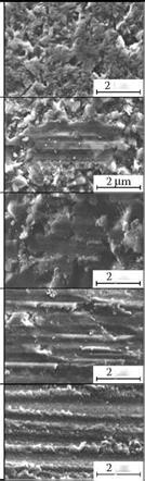
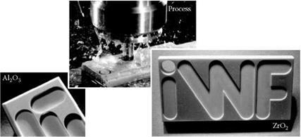
These results show that ultrasonic-assisted grinding ensures the machining of ceramics in terms of high economic efficiency and component quality. Through the variety of kinematic process variants, it is possible to machine different geometrical elements on brittle-hard materials (Figure 20.16).
|
|
[1] Depth of cut per pass should be kept in the range of 2 to 5 pm. Dressing forces may be as high as 100 N so rigid tool support is again critical.
• Resin CBN and diamond wheels can be trued with similar small grit tools (or “nibs”) to those used for vitrified CBN. Carius [1984] reports that diamond form blocks are also used to dress resin CBN wheels. The author is not aware of any reports yet using needle diamond blades, although it is to be expected. However, these wheels need to be subsequently conditioned, which is discussed in a separate section below. Vitrified diamond wheels, if containing a high porosity, may also be trued with diamond nibs. Dense hot — pressed wheels, however, must be trued and conditioned with conventional abrasive wheels and blocks.
[2] The increased rate of vibration amplitude for the wheel regenerative chatter is much slower than that of the workpiece regeneration type.
• The roots exist with the constant interval of 1/Ts or 1/Tw in the imaginary axis, where Ts and Tw are the rotational period of the grinding wheel and the workpiece, respectively. This result explains the fact that the chatter vibration observed is accompanied by an amplitude modulation.
• The chatter frequency is always higher than the natural frequency of the mechanical system.
[3] Flattening
• Microcrystalline grain splintering
• Partial grain break-off, and
• Total grain break-off
9.3.2 A Combined Wear Process
The strength of the particular wear process depends on the process parameters and on the grain and bond properties. The character of the wear process is governed by contributions from thermal and mechanical wear, which are determined by machining parameters, cooling and lubrication conditions, and process kinematics. Grinding wheel properties are determined by the stability and
[4] Centrifugal force from the balls
• Hydrodynamic pressure from the oil lubricant
• Thermal expansion from temperature differences due to frictional heat generation causes a temperature gradient between the inner and outer ring
• Thermal expansion of the balls
• Expansion of the inner ring due to centrifugal force
[5] Workpiece jammed
• Loss of coolant supply (sensor failure)
• CNC operator error
• Grinding wheel with steel core (e. g., electroplated) lost its coating and generated excess heat from rubbing on the part
[6] The components can be processed in a series of inexpensive 3-axis grinders with a single grind operation per machine. This can be done either one component at a time (Figure 16.27) or ganged up in series (Figure 16.28).
• The components can be ground on several surfaces in a single clamping on 4- or 5-axis grinders using a combination of tilt and/or rotational axes to present the various grind
[7] High-volume dedicated manufacturers with near net shape parts are converting primarily to vitrified CBN wheels in water-based coolant in combination with hard-point mounting for workholding.
• High-volume dedicated manufacturers with near net shape parts willing to grind in oil are converting to plated CBN in combination with hard-point mounting for workholding.
• High-volume dedicated manufacturers with high stock castings either remain with conventional creep feed wheels in conjunction with traditional CDCF or recent VIPER
[8] Use oil-based coolant instead of water.
• Use electroplated CBN wheels instead of bonded wheels [smaller Cr]. For life as well as for lubrication, these wheels are best used with oil.
• Use very high workspeeds (or very deep depths of cut).
• Use CBN instead of alox.
[9] Accuracy of the machine setup affects parallelism and size accuracy
• The shape of the grinding wheels affects roundness
• Wheel dressing affects surface roughness
• The composition of the grinding wheel affects grinding forces, process stability, wheel wear, temperature rise, and surface integrity
• Wheel wear affects consistency of size accuracy
• Rounding geometry affects elimination of out-of-roundness (OOR)
• Friction affects speed control
• Process fluid (coolant) affects cooling, flushing, process lubrication, and avoidance of wheel loading
• Machine and workpiece dynamics affect process stability and avoidance of vibrations
• Rotating masses, motors, drive belts, and feed-drives affect forced vibrations.
[10] vf h = — к-d ■ —
[12] f0/nw should not be an integer.
• ns/nw should not be an integer.
• nd/nw should not be an integer.
• nd/ns should not be an integer.
[13] Automated part feeding with bowl feeders, air cylinders, electric drives, and so on
• Automatic size gauging with air gauging, electronic transducers, and so on
• Automated checking of door closure or other safety features
• Automated size compensation using servo drives
• Automated grinding wheel dressing