
As in the case of external cylindrical grinding, internal cylindrical grinding is also classified as
• internal cylindrical peripheral crosswise grinding (plunge grinding) or
• internal cylindrical peripheral longitudinal grinding (longitudinal grinding).
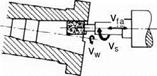
The kinematics of internal cylindrical grinding is identical to that of the external cylindrical grinding methods between centres already described. The equations derived there for the specific material removal rate are thus valid here as well. Some application examples are shown in Fig. 6-60.
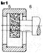
While the grinding of various notches (b.) involves pure plunge grinding and inside tapers (c.) involve longitudinal grinding, in example (a.) a combination of both methods is used. After a radial infeed, there is a movement lengthwise, since the surface to be machined is in this case wider than the grinding wheel.
The workpieces have to be clamped on the outer edge, as accessibility to the inner hole must be guaranteed. This can be achieved by means of a three-jaw — chuck as well as, for example, by means of gears with the help of a special construction. In this case, the gear is tightened by means of the teeth system. The disadvantages of tightening the components in a jaw chuck in comparison to clamped
 |
|
 |
 |
between centres is reduced radial precision as well as deformation of the components caused by the jaws. The last point is especially relevant in the case of thin — walled components (e. g. roller bearing rings). After relaxing the elastic deformation, the roundness of the machined surface is thereby no longer given.
a. grinding of b. simultanious grinding c. grinding of a taper bore a roll path of several different bores
with a wheel set
Fig. 6-60. Internal cylindrical plunge and longitudinal grinding for different applications
In internal cylindrical grinding, the contact arc between the grinding wheel and the workpiece is considerably longer, compared to external grinding operations. In this way, evacuating the chips and maintaining sufficient supply of cooling lubricant at the contact zone is more difficult. For this reason, grinding wheels must be utilised that allow for a so-called free cut at low pressure force and low contact zone temperatures. Such grinding wheels are characterised by a relatively large grit size, low hardness and an open structure.
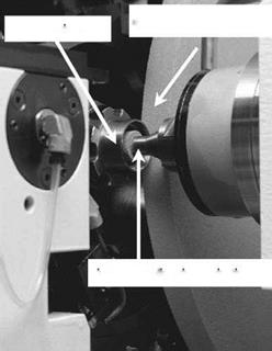
Fig. 6-61 shows an arrangement for internal and external machining of a liner by grinding. When grinding longer holes with a small diameter, there is a danger that the far-overhanging spindle will be considerably deformed. As a result of such deformations, undesirable deviations in shape and dimension results such as conicity (infeed grinding) and widening of the hole ends (longitudinal grinding).
The employable cutting speeds for small tools are often low, since the high spindle speeds necessary cannot be realised or only at considerable cost. The advantages of high cutting speeds (reduction of forces, surface quality improvement, wear reduction) can therefore not be brought into play for the most part. Moreover, the grinding wheels — because of their small dimensions (less grains are engaged more often) and low hardness — are subjected to a high radial wheel wear.
For the reasons mentioned, usually only small material removal rates are realisable in internal cylindrical grinding.
 external cylindrical grinding
![]() internal cylindrical grinding
internal cylindrical grinding
Fig. 6-61. Internal cylindrical grinding (Buderus Schleiftechnik)