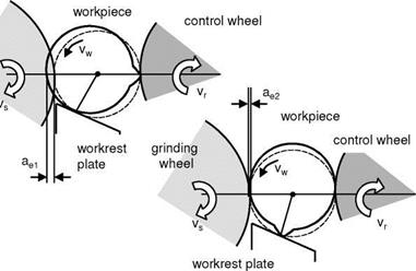
Under consideration is the grinding gap arrangement shown in Fig. 6-50. When dealing with geometrical process stability in centreless grinding, we proceed from the assumption that the workpiece constantly abuts the three contact locations S, A and R during the process [GURN64, ROWE65, SCHR71]. The machine components encompassing these system boundaries are considered ideally rigid.
A deviation from the circular form once present (here simplified as a single elevation) causes a displacement of the workpiece at the workrest plate or the control wheel, thereby temporally altering the cutting depth of the grinding wheel. In this way, the circular form deviation regenerates itself at another location of the circumference. In this case, already an incorrect grinding of the component in the first contact between the grinding wheel and the workpiece is sufficient as a starting roundness error to initiate geometrical instability.
This regenerative effect of the rounding process is a central problem of centerless grinding and can only be controlled by an appropriate choice of grinding gap geometry. At given wheels and workpiece diameters as well as a support angle value determined from the perspective of the introduction of force, there only remains the parameter of altitude h.
We distinguish between geometrically stable and unstable grinding gap settings. If the process runs with geometrically stability, eventual deviations from the circular shape are removed in the course of the process. In an unstable process,
one or more cylindrity deviations develop. The stability cards adapted from Reeka known to industry evaluate the geometrical stability of various grinding gap geometries (Fig. 6-51). In the cards, the polygon to be expected on the workpiece circumference is listed as a function of the grinding gap geometry so that a selection of a suitable grinding gap scenario is made possible according to these cri — terea.
![]() grinding wheel
grinding wheel
|
Fig. 6-50. Depth of cut alterations due to rotating cylindrity deviations [FRIE04] |
Even if geometrically stable conditions exist, wave numbers below a polygon order of size ten should generally be avoided, as these results in relatively large deviations from the circular shape. On the other hand, a marked polygonal shape approximates a circle well if it has a sufficiently high order and thus a large wave number. This is ground in the decreasing maximum penetration depth e of the grinding wheel into the workpiece with increasing wave number orders (Fig. 6-52) [FRIE04, REEK67].
For the process output, it is of importance how many rotations are available for the removal of the roundness errors and which stock allowance is ground off in each workpiece rotation. The parameter necessary for this is the overlap ratio U which indicates the number of rotations that the workpiece undergoes during the process. For centreless plunge grinding, the overlap ratio is calculated as follows:
![Подпись: Fig. 6-51. Card of stability (dr/ds = 0.6) [REEK67]](/img/3149/image256.gif) |
For throughfeed grinding, the overlap ratio U is determined purely geometrically by
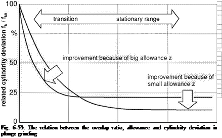
Fig. 6.53 makes it clear that the cylindrity deviation based on the input value at first improves very quickly with the overlap ratio, but then does not fall below a certain end value.
A larger stock allowance z leads in the transition area with a small overlap ratio to an improvement in shape, since the higher chip thickness resulting from this leads to the removal of larger amplitudes of cylindrity deviation in the grinding process. This reverses however in the stationary region of the curve into a disadvantage. There, fluctuations in the grinding process and external disturbances make themselves known, especially with larger depths of penetration. Besides a geometrically stable grinding gap design, a minimum overlap ratio value must be
 |
guaranteed in order to reach minimal roundness errors. Here, a large stock allowance initially provides for quick work progress [MEIS80].
As explained above, a total guarantee of small circular form deviations cannot be gained from geometrical stability alone. For an optimal process design, a number of other action mechanisms must be considered and calibrated with each other [KOEN72, KOEN82, KOEN84, SLON56].

