
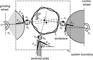
The simultaneous bearing and machining of the workpiece lateral surface can lead to roundness errors typical of the process that develop as polygons on the workpiece circumference. The model of the workpiece clamped in the grinding gap (Fig. 6-49) shows that the contact zone properties at the grinding wheel, control wheel and workrest support are crucial for a stable process.
|
Fig. 6-49. Model of the workpiece clamped in the grinding gap [FRIE04, SCHR71] |
Several causes of roundness errors in centreless grinding can be differentiated [FRIE04, FURU70, KLOC04]: [1]
bration of the grinding system because of excessive force actions, on the work — rest plate for example. As a result, the workpiece depth of cut changes periodically, leading to components that are not round. For integral rpm ratios of grinding wheel and workpiece rotation, cylindrity deviations arise because it is always the same grinding wheel and component areas that make contact. Further influences are discontinuous depth setting motions caused by the infeed device, inhomogeneities in the workpiece material, variances in spindle rotation speeds, wear formations, system flexibility, friction, differences in hardness in the grinding tools and dressing conditions.
• Separately excited vibrations, external disturbances
External disturbance variables include surrounding temperature or separately excited vibrations transmitted by the equipment foundation. They too have an essential influence on the formation of component shape errors, as in any machining process.
The workpiece circumference is never formed exclusively as the result of one instability. It is always an interaction of several types of vibration types and causes that interact with each other and merge into each other [FRIE04, KLOC04, KOEN72, KOEN82, KOEN84, SLON56]. In the following, we will go into detail into the geometrically caused circular form errors characteristic of the centreless grinding process.