Among cylindrical grinding techniques, centreless methods have an exceptional position with respect to their process structure and area of application. Centreless grinding’s main area of use is in large batch and mass production.
While the workpiece is led during grinding between centres in its rotation axis, its position in centreless grinding is determined by a three-point positioning between the grinding wheel, control wheel and workrest plate. The component is simultaneously conveyed to its peripheral area and machined.
Since the material removal process corresponds to that of other cylindrical grinding methods, we concentrate in the following on only method-specific features. Like grinding between centres, centreless grinding is also subdivided according to the orientation of the main feed direction.
In centreless plunge grinding (external cylindrical peripheral plunge grinding), the grinding wheel is moved radially towards the workpiece. With these technique kinematics, rotation-symmetrical parts can be produced, for example, bearing carriers of camshafts, valve tappets, jet needles, rotor axes and ball studs.
In centreless throughfeed grinding (external cylindrical peripheral longitudinal grinding), the workpiece is moved in the direction of the grinding wheel rotation axis. This technique is a typical mass production process of components with cylindrical, conical or spherical working surfaces. Working examples are bars, bolts, axles and roller bearing elements.
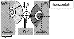
The grinding and control wheels as well as the workrest plate can be arranged horizontally, vertically or angularly, whereby the horizontal design is the most common (Fig. 6-46) [SLON56]. When grinding heavy workpieces, the horizontal construction leads to a high friction momentum on the workrest plate and low pressure force on the control wheel. The rotation speed of the workpiece cannot be controlled as well as a result. In order to avoid this, the grinding and control wheels can be arranged at an angle. In this way, part of the workpiece weight force is deflected to the control wheel, so that the normal force on the workrest plate is diminished. The friction momentum is reduced and the workpiece is brought to rotation faster. In the vertical design, besides the high pressure force between the workpiece and the control wheel already mentioned, a favourable supply and removal of heavy workpieces is ensured [HOFM78, WENN75].
Besides the primary methods of plunge and throughfeed grinding, there are also many other component-specific technique variants and machine constructions, for example, combined transverse and plunge grinding, face grinding, centreless internal cylindrical grinding, which we wish merely to point out.
The advantages of the above-mentioned methodological principles of centreless grinding in comparison with cylindrical grinding are evident:
• the linear support of the workpiece makes it possible to machine flexible and brittle workpieces with high material removal rates, i. e. with large grinding forces and minimal deformations.
• the workpiece does not need to be clamped, eliminating potential fault sources caused by clamping and reclamping.
• workpiece loading is easy to automate. In throughfeed grinding, a continuous feed is customary, eliminating workpiece loading times.
• in throughfeed grinding, parts can be machined that well exceed the grinding gap length.
• when the machine is carefully adjusted parallel to its axis and the dressing processes are adapted correctly, centreless grinding processes can achieve circular and cylindricity errors of <1 pm. Depth of cut errors due, for example, to grinding wheel wear or thermal warpage directly influence the workpiece diameter. When grinding between centres, diameter-related component errors due to radius alteration are twice as large.
 |
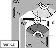 |
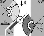 GW = grinding wheel CW = control wheel
WP = workrest plate
g = gravity
x = feed
Fig. 6-46. Tool arrangements in centreless grinding machines
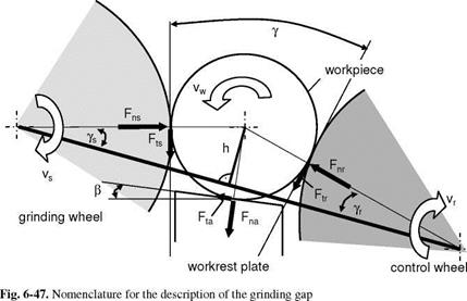
The grinding gap is defined by the configuration of the workpiece, grinding wheel, control wheel and workrest plate. Fig. 6-47 shows the motion relations that are valid in principle for both plunge and throughfeed grinding.
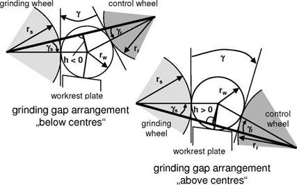
The position of the workpiece is statically determined by contact with the grinding wheel, workrest plate and the control wheel. Linking the grinding wheel and control wheel centres defines the reference line to which the workpiece centre is offset upwards (above-centre grinding) or downwards (below-centre grinding) (Fig. 6-48). The distance between the connection lines of the grinding and control wheel centres and the workpiece centre is designated as the altitude h or centre height h. Since in established machine concepts the control wheel unit is often adjustable in height, the altitude can by all means deviate from the vertically meas
ured workpiece height. Depending on the manufacturing task at hand, a sub-centre setting can be advantageous with respect to process stability.
Tangent angles are defined as the angles that encompass the contact tangents of the workpiece at the grinding/control wheel with the perpendicular.
|
|
|
Fig. 6-48. The grinding gap arrangements “above centre” and “below centre’ |
For plunge grinding, the grinding wheel tangent angle ys and the control wheel tanget angle yr are calculated as
The sum of both of these angles corresponds to the tangent angle у
)
The control wheel must slow down the workpiece during the grinding process. Except for a small amount of slipping, the peripheral speed of the control wheel vr thus corresponds to the workpiece peripheral speed vw, which has similar values to those in cylindrical grinding between centres. Centreless techniques typically involve down grinding. In order to create the necessary force transmission by friction between the workpiece and the control wheel, a control wheel specification of fine-grained corundum in a rubber bond with a closed structure is often selected.
The workrest plate (also called support or work rest blade) is engaged frictionally with the workpiece. It must be wear-resistant, since wear leads to component shape and misalignment errors. For this reason, carbide supports or coated running surfaces (e. g. with PCD coatings) are used. For small batches, workrest plates made of tool steel or grey cast can also be used. The inclination angle в is defined as the helix angle at the workpiece support surface to the horizontal.
Since in machining flexible workpieces only a little space remains in the grinding gap between the wheels, the workrest plate must often be very narrow. It is thus the weakest link of the grinding gap in the flux of the machine. Designing the workrest plate in a way which meets stress requirements is thus extremely important, because workrest plate vibrations spread directly to the grinding process, leading to dynamic instabilities and component faults. Furthermore, the support surface should, in accordance with the friction angle, be so inclined in contact with the workpiece that the force on the workrest plate is directed in the normal direction as much as possible and in the tangential as little as possible, so that no bending load occurs.
The process forces effective at the three contact locations of the workpiece in the grinding gap are analysed into their normal and tangential components. In consequence, these are designated with tangential force (Ft…) and normal force (Fn…) at the grinding wheel (…s), control wheel (…r) or workrest plate (…a). In through-
feed grinding, axial forces answer the purpose of workpiece transport, and in plunge grinding, they serve to fix the workpiece in the grinding gap.

