
External cylindrical peripheral plunge grinding, also called external cylindrical infeed grinding, is utilised for machining bearing carriers, shaft cranks and grooves. Fig. 6-35 shows the schematic arrangement of the grinding wheel, workpiece spindle and the dressing spindle as well as the axes and the direction for the feed setting.
 |
The infeed can be subdivided into several process phases, which are distinguished by the fact that, with each further phase, there is a smaller specific material removal rate. During spark-out, no radial infeed setting takes place. In this way, shape errors attributable to deformations caused by machining forces, can again be partially balanced out. Furthermore, by lessening the machining rate towards the end of the process, we can improve the surface quality.
In order to guarantee consistent quality in batch production, a measuring device is often employed, which measures the workpiece in the x — and y — direction before grinding in order, for example, to determine exactly the position of the cylinder to by ground as well as the adjacent shoulder. By doing this, the radial safety measure can be reduced, which saves time and lessens the danger of collision with the
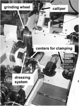
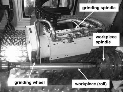
abutting shoulder. Fig. 6-36 shows a photograph of an external cylindrical grinding machine for peripheral plunge grinding.
|
Fig. 6-36. External cylindrical grinding machine from the Junker company |
One variant of cut-in grinding is angle cut-in grinding. High plane shoulders and peripheral areas can be produced in one infeed by means of an angled grinding wheel rotation axis, Fig. 6-37 [GOER86]. With this manufacturing method, there are clear time advantages in comparison with straight infeed grinding. In particular, the angled position of the grinding wheel in contrast infeed grinding reduces the grinding contact length on the plane shoulder, reducing the danger of thermal structural damage. The advantages are most evident in processing shaft crank with considerably varying diameters, which are machined with a wide grinding wheel or a set of grinding wheels. Cutting speed differences, which appear in straight infeed grinding when machining these components, can be balanced out to the greatest extent by setting the grinding wheel at an angle.
Infeed with a wide set of grinding wheel, where all functional areas are machined simultaneously, is a highly productive, yet also very inflexible method. With such a disc set, often only a single geometry can be produced. This method is therefore only practical with a certain batch size. Because of the wide grinding wheel making contact, strong forces take effect, so that, besides the workpiece de-
 |
 |
flection, one must also be mindful of workpiece drive with high torque. Especially when machining thin, slender components, the use of a steady rest is necessary in order to avoid impermissibly high deformation of the workpiece due to machining forces.
external cylindrical external cylindrical
peripheral peripheral
plunge grinding angle grinding
Fig. 6-37. External cylindrical peripheral plunge grinding with straight and angled infeed [GOER86]
For external cylindrical infeed grinding with a straight infeed, material removal volume is calculated as follows:
For a small grinding measure z, which as a rule is in the realm of a few tenths of a millimetre and is very small with relation to the workpiece diameter, the calculation formula (6.46) can be simplified to:
z
Vw =n dw—• bf (6.69)
Here it is irrelevant whether the unfinished or finished component diameter is used for dw. If we divide the material removal volume Vw by the width of the active grinding wheel profile and relate the result to the cutting time tc, we obtain as a parameter the specific material removal rate Q’w z
with v = to:
2tc
For angle infeed grinding, the specific material removal rate can be determined in the same manner, whereby large differences in workpiece contour diameter must be taken into consideration in the calculation.
External Cylindrical Peripheral Longitudinal Grinding
 |
External cylindrical peripheral longitudinal grinding between centres is used to manufacture cylindrical and conical workpieces, if the workpiece length to be machined is much larger than the grinding wheel width. The main field of application of this grinding technique is in machining print cylinders, cylinders for paper manufacture and for steel mills. In this technique, the grinding wheel moves along the workpiece, which is clamped between centres. At the reversal points, the feed motion occurs normal to the workpiece surface. After the transition into the feed motion with the set speed, one side of the grinding wheel comes into contact with the workpiece (Fig. 6-38).
Generally, it is possible to remove the total allowance in only one grinding stroke, designated as peel grinding, or in several strokes. These variants are distinguished in a manner similar to deep and pendulum grinding in the case of flat grinding. Especially appropriate for this are grinding wheels with particularly
wear-resistant grain materials like cBN, since in this case the stress on the grinding wheel edge is much higher than in pendulum grinding with only small radial depths of cut.
Fig. 6-39 shows an external cylindrical grinding machine for peripheral longitudinal grinding.
|
Fig. 6-39. An external cylindrical grinding machine from Buderus Schleiftechnik |
As a result of grinding wheel wear, a step-shaped wear profile is formed that is characteristic for external cylindrical peripheral longitudinal grinding [WUEN92]. This causes the width of the roughing zone to get constantly larger. The width of the spark-out zone bsa diminishes correspondingly.
In some applications, the grinding wheel is already shaped with a roughing zone geometry during the preparatory stage. In this way, a roughing zone which changes in an unregulated way at the start of the process is avoided. The transition between the roughing and spark-out zones can sometimes be executed with an additional finishing zone.
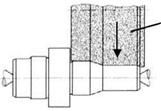
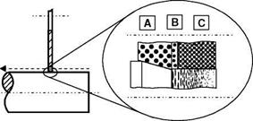
Fig. 6-40 illustrates the various zones of a grinding wheel for the external cylindrical peripheral plunge grinding of cylindrical workpieces. In zone A, the roughing zone, the largest amount of material is removed. The workpiece surface created in this area is grinded again in the subsequent workpiece rotation. The influence of this zone on the workpiece surface finish is thus minimal. A sufficiently large chip space and a high grinding wheel effective surface roughness and the main requirements on the grinding wheel roughing zone. The finishing zone (B) has only a small width, which usually corresponds to the feed af. Here, residual material is removed and the workpiece surface is created to a large extent. A high cutting edge number with minimal chip spaces is advantageous for this purpose. Theoretically, in the spark-out zone (C), no more material removal takes place. By means of the smoothing of the roughness peaks which occurs here, the surface quality is improved. A large amount of active grain cutting edges as well as flattened abrasive grains are advantageous for this [HEGE98].
|
Fig. 6-40. Generating the workpiece surface for roughing zone (A), finishing zone (B) and spark — out zone (C) [HEGE98] |
The conditions of engagement in external cylindrical peripheral longitudinal grinding are influenced to a great extent by the geometry of the grinding wheel roughing zone, Fig. 6.41. With a cylindrical grinding wheel profile with a straight roughing zone, for each workpiece rotation a ring-formed element with the height of the cutting depth ae and the width of the cutting width ap is removed. The unworn grinding wheel has a roughing zone width of bss, which corresponds to the cutting width ap. The specific material removal rate Q’w is calculated generally from the quotient of the material removal rate Qw and the effective grinding wheel width bs eff (Fig. 6.41), resulting in
Since the effective grinding width bs eff is equal to the cutting width ap, we obtain for the specific material removal rate
In the case of straight roughing zone geometries, the specific material removal rate is independent on the axial feed rate vfa. The latter results from the cutting width ap and the workpiece rotational speed nw, resulting in
For a conical roughing zone, this is many times larger than the cutting width ap. The roughing zone width bss is computed with the allowance z and the profile angle a, yielding
In the case of identical machine parameters, stress on the conical roughing zone is less than that on a straight roughing zone, since material removal is distributed across a larger grinding wheel width. The conical roughing zone is subdivided into three areas (Fig. 6-41). In area I, the specific material removal rate Q’w increases linearly. Then there is an approximately constant specific material removal rate (area II). In area III, the specific material removal rate drops in the direction of the finishing zone back to zero. In area II, the depth of cut ae is linked with the cutting width ap by the profile angle a, resulting in
ae = ap • tan a. (6.75)
The effective grinding wheel width bs eff is equal to the cutting width ap in the case of a conical roughing zone as well. The specific material removal rate Q’w in area II thus results as
The specific material removal rate of the conical roughing zone is thereby contingent on the cutting width ap and thus also on the axial feed rate vfa. Lessening the grinding time by increasing the axial feed rate thus leads directly to more grinding wheel stress. The advancement of wear progresses through the constant grinding wheel wear in area II equidistant to the initial contour. At constant workpiece allowance z, the roughing zone width increases with a falling profile angle a. With this, the specific material removal rate Q’w is reduced.
However, since the roughing zone geometry changes its form due to wear and, according to the particular application, other roughing zone geometries can become involved, the specific material removal rate is not effective for comparing and evaluating longitudinal grinding processes. Instead, the material removal rate is used:
The machining time is directly proportional to the feed rate. One can only increase the feed however within certain limits, since, on the one hand, the overlap ratio decreases with increasing feed, while on the other hand, the grinding process becomes unstable at high feeds and tends to clatter.
With a linear contact between the grinding wheel and the workpiece, for the overlap ratio of the spark-out zone Ua with the spark-out zone width bsa and cutting width ap comes we obtain
Technique-specific difficulties in external cylindrical grinding with a fixed workpiece often result from workpiece mounting. If one works between fixed centres, a faultless workpiece concentricity is only possible when both the centres as well as the workpiece centrings are designed properly. An unsymmetrical material distribution can lead to undesired displacements, especially at higher workpiece rotational speeds. Problems are common when grinding long, slender workpieces,
which, because of high cutting forces during roughing, deflect so much that there are still formal defects even after smoothing and spark-out [WUEN92]. Especially in the case of slender components with high dynamic flexibility, regenerative chattering can occur on the workpiece side [ALLD94].
When grinding between centres, the selection of workpiece drive also has a decisive influence on possible form errors and process stability. If the drive torque is not transferred to the workpiece by the driver free of shear forces, the workpiece can shift. This can lead to altered engagement conditions in the grinding contact zone and to deviations from the circular form.