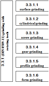
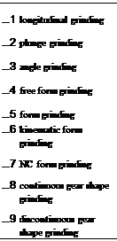
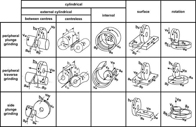
Machining processes of workpieces with grinding wheels is fundamentally distinguished according to DIN 8589, or ISO/ DP 3002/ V. Subdivision is carried out with serial numbers (ON), which are currently in seven figures and describe each method according to its systematics. Proceeding from the upper division ’’separation” in manufacturing processes, we have the further subdivision “machining with geometrically undefined cutting edges” (ON 3.3) right up to “grinding with rotating tools” (ON 3.3.1). Further subdivision within each particular method takes place in accordance with Fig. 6-30. Here, we distinguish each method according to its type, the surface to be machined, the working face used and the type of feed motion [DIN78a].
 |
 |
 |
|
position of serial number 3. 4. 5. 6. 7.

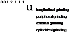 |
Fig. 6-30. Classification of methods for machining with grinding wheels in accordance with DIN 8589 [DIN78a]
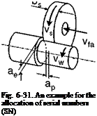
For example, in the case of external cylindrical peripheral longitudinal grinding with ON 3.3.1.2.1.1.1, the grinding wheel’s peripheral surface engages with the outside of the round workpiece and the feed direction of the grinding wheel goes alongside the workpiece rotation axis (Fig. 6-31).
Particular processes can be further classified in addition to the seven-digit serial number. This includes distinctions in down and up grinding, pendulum and creep feed grinding as well as the case of rotation-symmetrical workpieces, whether the latter are machined between centres or are mounted without centres.
The grinding operation is characterised by a continuous material removal which results from the coaction of cutting and feed movements. The feed movement can itself be composed of several, kinematically coupled movements. In the case of some methods, there is also a motion for depth setting, which determines the thickness of the layer to be removed ahead of time. The depth setting motion can be conceived as incrementally executed components of a feed motion.
In Fig. 6-32, cutting motions are characterised by the cutting speed vc, the workpiece speed vw and the main feed velocities in the axial, radial and tangential directions vfa, vfr and vft. The feeds in these three directions are labelled in accordance with the indexes fa, fr and ft. The grinding wheel engagement is characterised by the depth of cut ae and the feed/cut width ap. From these parameters, the material removal rate Qw, which is a parameter for the material volume removed per time unit, can be calculated. Fig. 6-33 gives an overview of the calculation formulae for the various grinding methods.
For peripheral plunge-grinding methods, after calculating the material removal rate Qw and subsequent division by the width of the active grinding wheel profile bs eff, we obtain the specific material removal rate Q’w. The parameter specific material removal rate Q’w allows for a comparison, disregarding particular methods, of the temporal material removal independent of the width of the grinding wheel profile used. Fundamentally, a specific material removal rate Q’w is calculable for other methods as well, whereby this parameter is contingent on the respective local, active width of the grinding wheel profile being used and the appertaining depth of cut ae. The grinding wheel width bs in external cylindrical peripheral longitudinal grinding, for example, does not correspond with the local active grinding width bs eff of the grinding wheel roughing zone. The determination of the specific material removal rate Q’w requires exact knowledge of the geometry of the grinding wheel profile and the feed movements active in the contact zone.
|
|||||||||||||||||||||||||||||||||||||||||||||||||||||||||
