In the following, parameters will be introduced which characterise the grinding process.
Material removal Vw describes the amount of workpiece material removed in the grinding operation. When grinding cylindrical components, the material removal Vw is calculated as a function of the diameter of the unfinished part dwA, the final diameter dwE and the grinding length lw.
(6.10)
During grinding, often only a small stock allowance z (relative to the diameter) is removed, so that for small values of z the relation
.
Accordingly, the material removal for flat grinding is calculated as a function of the grinding length lw, the grinding width bs eff and the total depth of cut ae tot, resulting in
In praxis, material removal is often related to the width of the active grinding wheel profile in order to obtain a parameter independent of the initial width and to improve comparability of experimental results. The specific material removal V’w is defined as:
The material removal rate is defined as the volume of material removed per time unit, thus corresponding to the differential quotient of material removal and time. Assuming a constant material removal rate Qw over time, by integration follow
For instance, for external cylindrical plunge grinding we obtain
and for external cylindrical longitudinal grinding
In order to compare different processes, we relate the material removal rate Qw to the effective width of cut bs eff, thus obtaining the specific material removal rate
QV
|
Є |
 |
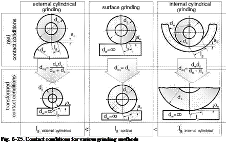
The equivalent grinding wheel diameter deq is a parameter used to compare the engagement conditions of various grinding techniques (Fig. 6-25). It takes into consideration that in the external cylindrical grinding, surface grinding and internal cylindrical grinding varying contact conditions develop despite equal depths of cut [STEF83].
The parameter deq corresponds to the grinding wheel diameter in surface grinding, in which the contact conditions would be the same as in the method selected. The equivalent grinding wheel diameter
is influenced both by workpiece and tool curvature. In the denominator of the equation, the positive sign is valid for external, the negative for internal cylindrical grinding. According to the definition, the equivalent and actual grinding wheel diameters coincide during surface grinding (deq = ds).
The kinematics of the grinding process changes as a function of the speed ratio q, which relates the grinding wheel peripheral speed and the workpiece speed [GROF77]. The kinematic contact length lk takes into consideration that every abrasive grit moves on a cycloidal path relative to the workpiece. In up cylindrical grinding, this is negligibly longer than the geometrical contact length and can be approximated with:
The calculation of the geometric contact length proceeds from ideally even bodies. If we consider the average surface roughness Rz of the workpiece, which must be compensated with a correspondingly increased depth of cut (Rz + ae), we obtain the effective geometrical contact length
and, accordingly, the effective kinematic contact length
For speeds usual in praxis, the difference between the geometric and kinematic contact lengths is slight, and therefore it is not absolutely necessary to distinguish between them.
Cutting Edge Number, Chip Thickness and Chip Cross-Sectional Area
In the contact area between the tool and the workpiece, there is always a multitude of cutting edges engaging simultaneously, so that material removal emerges as sum of many individual cuts.
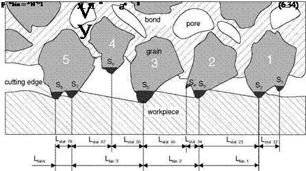
Fig. 6-26, above, is a simplified representation of a cut perpendicular to the rotation axis of a grinding wheel whose circumference is engaged. All grits protruding from the bond are static cutting edges, the area between the cutting edges is the cutting space or chip space. Since one grain can certainly have several cutting edges, the distance between the static cutting edges does not coincide with the distance of the individual grains. To characterise the cutting space structure (grinding wheel topography), we do not as a rule use the cutting edge distance shown in Fig. 6-26, but rather its reciprocal value, i. e. the number of cutting edges per unit of length (Sstat). Further parameters are the number of static cutting edges per grinding wheel surface unit (Nstat) and the static cutting edge density (Cstat) per volume element of the cutting space.
By superimposing the movements of the grinding wheel and the workpiece, we obtain the cutting edge paths in the material. Only part of the cutting edges protruding from the bond, the kinematic cutting edges, take active part in material removal. The amount of kinematic cutting edges Skin is as a rule less than that of static cutting edges [STEF83].
 |
The number of kinematic cutting edges Nkin per mm2 of the grinding wheel circumference can be calculated from the relation
Equation 6.34 shows that the number of kinematic cutting edges increases with higher feed velocities. At a constant specific material removal rate Q’w, we now obtain from equation 6.35 the average number of cutting edges momentarily engaging Nmom [KOEN71, KOEN80a, PEKL57, ZEPP05].
If we consider the case of surface grinding, at a constant specific material removal rate Q’w, constant grinding wheel diameter ds and constant cutting width, we obtain from the geometric contact length lg the relation in equation 6.36. The exponent a is set at a = 1/3 for the following calculations according to the literature [KASS69, PEKL57, WERN71]. For increasing table feed velocities vw, we now obtain a decreasing average number of cutting edges momentarily engaging
Nmom.
The maximum undeformed chip thickness is a measure for stress on the cutting edge. For single-grain cutting, i. e. if we consider a grinding with only one grain, the chip thickness can be approximated as follows [WERN71].
In the case of peripheral milling, i. e. material removal with geometrically defined cutting edges, due to the equal cutting edge distance L and the equal distance of the cutting edges of the tool rotation axis, the engagement conditions are always the same assuming a homogeneous material structure. In the grinding process however, they vary because of random cutting edge distribution and form. Statistical methods are therefore necessary for a consideration of material removal behaviour. The geometry of the cutting edge engagement in grinding is described by the statistically averaged maximum undeformed chip thickness hcu max and the average chip length lcu. If we extend equation 6.34 from single-grain to multiple-grain cutting and additionally consider the statistical cutting edge density Cstat, we obtain according to Kassen and Werner [KASS69, WERN71]
However, the meaningfulness of both parameters lcu and hcu is limited by the fact that they were derived under ideal kinematic conditions. Since the cutting edges not only remove material, but also deform it, neglecting the mechanisms of chip formation and material behaviour is very noticeable for small depths of cut. The total chip cross-sectional area Acu, tot in a multiple-grain cut is the result of the sum of the chip cross-sectional area Acu of the individual grains or the quotient of the material removal rate Qw and the cutting velocity vc.
Calculation of the chip cross-sectional area Acu presumes a knowledge of the chip thickness hcu, max, which is generally obtained by means of equation 6.39. In the following calculations, we assume an isosceles triangle with the characteristic angle x as the basic grit form perpendicular to the cutting direction, from which we obtain the general dependence by inserting equation 6.39 in equation 6.41 [WERN71, ZEPP05].
 |
From this results the progression shown in Fig. 6-27 of the relative chip crosssectional area at the single grain Acu. The latter increases degressively with rising feed velocities. In contrast to this the number of cutting edges momentarily engaging Nnom diminishes exponentially with increasing feed velocities.
Grinding Force, Grinding Power and Grinding Energy
During grinding, a spatially directed force engages at every cutting edge. If we add up the vector sum of all simultaneous cutting forces Fci, we obtain the cutting force Fc:
It is composed of three components:
(6.43)
The behaviour of the normal force can be explained with the kinematic parameters [WERN71]:
According to the equation (6.44), the normal force based on the width of the active grinding wheel profile bs, eff is the product of the local chip cross-sectional area Acu and the kinematic cutting edge number Nkin integrated along the contact length lg.
The axial force Fa is directed parallel to the grinding wheel rotation axis. The tangential force Ft engages in the peripheral direction of the grinding wheel. From the normal force Fn acting radially upon the grinding wheel we can infer machine and workpiece deformation.
The quotient of the tangential force and the normal force is defined as the cutting force ratio [STEF83, VITS85]
It is used to characterise the friction conditions in the contact zone between the cutting edges and the workpiece and is a measure for the cutting ability of the grinding wheel and the effectiveness of material removal. But it should not be confused with Coulomb’s friction number p. Sharp grains lead to lower normal forces and thus to a higher cutting force ratio p.
Grinding experiments have shown that as a rule grinding forces at constant material removal rates decrease with increasing feed velocities. This is ascribed to the fact that with increasing feed velocities, chip cross-sectional areas also increase (equation 6.41) and the grain cutting depth is reached faster. With this, chip formation starts earlier and the amount of elastically and plastically deformed material is reduced [KOEN79a, ZEPP05].
of a volume element of a component.
How the various paths of grinding powers and energies affect temperatures in the component surface layer during grinding will be described — independently of material — in the following.
