
The efficiency of the cooling lubrication is not only determined by the cooling lubricant’s physical and chemical properties, but also by the method of supplying the fluid into the cutting gap.
For a sufficient supply of the contact area with the cooling lubricant, the cooling lubricant volume rate, the cooling lubricant discharge speed and the construction and position of the cooling lubricant nozzle are important.
 |
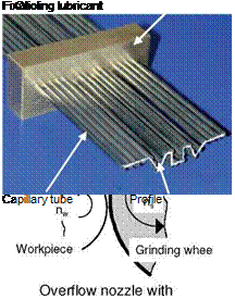 |

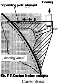
Fig. 5-8, I, shows a conventional overflow nozzle or free jet nozzle. In the case of this nozzle design, it is important that the cooling lubricant is not, as shown, extruded by the air cushion rotating with the grinding wheel. To obtain a sufficient supply at the grinding location, the discharge speed and with it the volume rate of
the cooling lubricant jet must be increased. This is all the more relevant the higher the grinding wheels circumferential speed is.
Above right (Fig. 5-8, II), an additional deflector is leading the cooling lubricant jet towards the grinding wheel so that lubrication is improved.
In the case of the shoe nozzle (Fig. 5-8, III), the nozzle geometry provides for a longer contact between the cooling lubricant and the grinding wheel surface than is the case for conventional overflow nozzles. Furthermore, the cooling lubricant’s drainage along the grinding wheel face is also reduced by the nozzle’s geometry. The essential purpose of shoe nozzles is to divert/remove the air cushion rotating with the wheel as well as to accelerate cooling lubricant supply to the rotational speed of the grinding wheel. The result is an improved wetting of the surface of the grinding wheel and avoidance of leakage volume flow. By considering these points, the cooling lubricant can be supplied in a more targeted fashion to the machining location, which makes possible a reduction of the applied volume flow. The longer contact length between the cooling lubricant and the grinding wheel, on the one hand, facilitates the acceleration of the volume flow to the circumferential speed of the grinding wheel, but the cooling lubricant can also penetrate into the abrasive grits in the case of porous grinding wheels. Because of the advantages of the shoe nozzle, it is unnecessary to use high pressures and high volume flows in supplying the cooling lubricant. The disadvantage of shoe nozzles is their geometrical inflexibility. For this reason, they are less suited to use in conventional grinding wheel operations, in which grinding wheel dimensions can change relatively quickly due to high wear. Shoe nozzles are to be recommended for use in external cylindrical grinding processes with superabrasive grinding wheels and high cutting speeds.
Another concept in cutting speed supply is the needle nozzle (Fig. 5-8, IV). In this case, the cooling lubricant is supplied by means of several small tubes. The tubes can be adjusted to fit the geometry of the grinding wheel or the workpiece to be processed. By means of an adjusted length of the capillary tubes, a laminar flow can be realised, so that the cooling lubricant flows from the nozzle in a directed way and with higher speed, and the profile is preserved across a certain length. Needle nozzles have proved useful especially in flat profile grinding operations on difficult-to-machine materials such as nickel-based or titanium materials causing less wear. The necessity of high-performance supply pumps is a disadvantage of needle nozzles.
In addition to the nozzle that guides the cooling lubricant to the cutting gap, further nozzles can be distributed around the grinding wheel in order to supply cooling lubricant radially onto the grinding wheel surface (Fig. 5-9). This is especially interesting for grinding tasks in which the grinding wheel is prone to clogging. These cleaning nozzles have the function of rinsing clogging particles from the surface of the grinding wheel. Purifying success can be inferred from the improvement in surface quality and from the reduction of grinding forces with increased amounts of nozzles. The effectiveness of these nozzles is contingent first
 |
and foremost on the high exit speed of the cooling lubricant, and thus on the impetus
The normal force in grinding is composed not only of forces resulting from the chip formation process but also of components originating from the hydrostatic and hydrodynamic pressure build-up of the cooling lubricant. To clarify this effect, Fig. 5-10 illustrates the components of normal force resulting for various cutting speeds and cooling lubricant volume flows.
Doubling the cutting speed from vc = 90 to 180 m/s leads to the desired reduction of that portion of the normal force caused by chip removal. In contrast to this, the fluid pressure force Fn, KSS behaves differently. At a specific cooling lubricant volume flow of 1.3 l/min per millimetre of grinding wheel width, the normal force components caused by the cooling lubricant remains constant, while these force components increase considerably already at 2 l/(minmm).
|
Material |
100 Cr 6 (62 HRC) |
|
Grinding wheel |
B126 GYB 200 |
|
Speed ratio |
q = 60 |
|
Spec. material removal rate |
Q’w = 40 mm3/ mms |
|
Cooling lubricant |
oil |
|
Spec. volume flow |
1.3 l/ min mm |
|
♦ Total force A Fuid pressure force ■ Grinding force |
2 l/ min mm ….. 1,3 l/ min mm —— 2 l/ min mm |
|
30 |
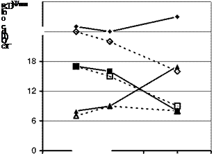 |
Fig. 5-10. Influence of coolant on the normal force during increasing the normal force
The fluid pressure force increases with the cutting speed as a function of the cooling lubricant volume flow and can exceed the grinding normal force according to the amount. The outcome is a total normal force that increases with the cutting speed. This fact becomes especially important in high-speed grinding.
The exhibited effects of the pressure build-up caused by the cooling lubricant in the grinding gap during an increase in the cutting speed make it clear how necessary it is to have a cooling lubrication system which is adapted to the requirements of the grinding process. The amounts of cooling lubricant necessary for high-speed grinding have been estimated variably, ranging from 10 to 30 l/(minmm). Fig. 5-11 shows the results from tests with minimum quantity lubrication, which were ascertained with a cooling lubricant volume flow which was significantly reduced in comparison with the values above. The cooling lubricant was supplied with a shoe nozzle optimised for high-speed grinding [TREF94].
An influence of the amount of cooling lubricant on workpiece roughness was not detected within the control variable ranges investigated in the grinding experiments. Roughness values are on the same level for coolant amounts typical in praxis as well as for drastically reduced amounts. Comparing the normal force components shows the influence of the cooling lubricant volume flow discussed earlier. The difference in force between various cooling lubricant amounts is all the more obvious the smaller the specific volume is. With small chip thicknesses, the amount of force caused by the cooling lubricant can far exceed that pure cutting force, so that reducing the cooling lubricant volume flow becomes advantageous.
Comparing the grinding efforts necessary for the process shows that a reduction in cooling lubricant volume flow diminishes grinding performance. The cause for this is to be found in the power loss caused by the braking effect of the cooling lubricant, which essentially depends on the amount of cooling lubricant.