The distribution of force and energy can be considered both microscopically with relation to the individual grits as well as macroscopically on the scale of the entire grinding wheel. In the following, we will begin with a microscopic observation and then expand this with macroscopic considerations.
The cutting force acting upon the individual grit during a cutting edge engagement can be broken down into a component FtS in the direction of the cutting
speed and a component FnS in the direction normal to this (Fig. 2-6). The quotient FtS/FnS is called the cutting force ratio p.
The cutting force of the entire tool is the vector sum of the cutting forces that act upon the cutting edges momentarily engaging with the workpiece. The cutting force ratio determined by the machine often largely corresponds to the average cutting force ratio of the individual cutting grits [RUBE67].
During the phase of pure material deformation, the force FnS, with which the cutting edge must be pressed into the workpiece, is considerably larger than FtS; the cutting force ratio thus assumes a relatively small value. As chip formation starts, the tangential force FtS goes up, and so the cutting force ratio increases.
Sharper cutting edges with a small cutting edge radius pS and/or greater friction allow for earlier chip formation during cutting edge engagement and lead to a — in comparison to duller cutting edges — larger cutting force ratio.
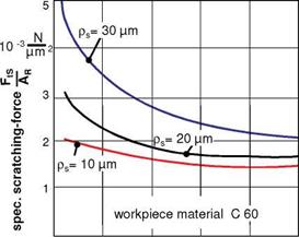
Scoring experiments, in which the engagement path of a particular grain is seen in analogy with the grinding process, can give us concrete information about the absolute magnitude of the cutting force components. For the experiments, the results of which are illustrated in Figs. 2-9 and 2-10, conical diamonds with varying peak radii pS served as the scoring tools [BUSC68, VITS85]. In order to obtain conveyable results, the measured tangential force is related to the cross-section of the scratched groove.
|
0 20 40 60 pm2 100 Scratch cross section AR Fig. 2-9. The cutting edge radius and scratch cross-section determine the specific scratching force along with friction |
With shrinking cross-sectional areas, the specific scratching force takes on very high values. This reflects the fact that the cutting edge rubs over the workpiece material with the flank face at small amounts of chip thickness, thereby only deforming it. Furthermore, the positions of the curves make it clear that, in the case
of dull cutting edges, there must be a higher cutting force due to the enlarged contact surface. If we broaden the specific scratch force in the numerator and denominator with the dimension of length, a volume controlled work results. The numerical value of the specific scratching force can then be interpreted as that work which is needed to produce a unit volume of score.
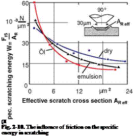
The influence of friction on the specific scratching force is also clarified by Fig. 2-10. For varying friction conditions, the specific scratching force reaches higher values with shrinking scratch cross-sections. For example, at small chip thicknesses, the material is only deformed by the cutting edge. Material removal is dominated by the mechanism of micro-groove formation. In the realm of small scratch cross-sections, an improvement in lubrication leads to a higher specific energy requirement, which can be ascribed to the proportionally increased workpiece material deformation. In comparison to scratching without cooling lubrication, with the use of emulsions or oil, an average of ca. 2 to 2.5 pm less scratch depth was realised. In the case of larger scratch cross section on the other hand, the influence of the tangential forces dropping with friction are dominant, so that emulsions and especially oil lower the specific energy requirement [VITS85]. By these machining conditions, the mechanism of microcutting comes to the fore.
 Workpiece material:
Ck 45N
Cutting material: Diamond
Workpiece speed: vw= 6,25 mm/s Scratching method: Lengthwise scratching Cutting speed: vc = 20 m/s
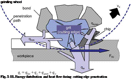
The mechanical energy present is transformed into heat basically in four places. Because of the large cutting edge radii, most of the heat generated consists of flank face friction and plastic deformation of the workpiece material. Heat is generated by friction at the chip surface and during chip cropping. Finally, in the case of bonded grains, a small amount of mechanical energy is also converted into heat as the bond rubs against the workpiece.
The main share of the energy inserted into the process is converted into heat. Thus, all system components involved in machining experience thermal stress or dissipate heat. The total heat flow rate qt spreads in the contact zone to the grinding wheel (qs), the workpiece (qw), the chips (qspan) and the cooling lubricant (qkss) (Fig. 2-11). How high the particular share of heat flow is depends on, among other things, the heat conduction coefficient of the workpiece material, the cooling lubricant and the grinding wheel as well as the heat transfer coefficient [JAEG42, STEP03].
 |
Heat flow into the workpiece can lead to a local rise in temperature. This increase in temperature can, depending on the magnitude and action time, produce thermal structural changes in the workpiece surface layer. The action time of the heat and the temperature level can be favourably influenced by applying a cooling lubricant.

