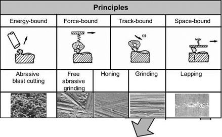
In addition to the geometry of the individual cutting edges, the way in which the hard material grains engage is also important. The four possible operating principles for this are represented in Fig. 2-5.
|
|
|
Fig. 2-5. Operating principles of cutting edge employment |
In the case of abrasive blast cutting, the grains are unbonded and collide with the surface of the workpiece. If the grains come up against a ductile workpiece material, a surface with small craters will result. Crater formation is associated with plastic flow processes, which result in a hardening of the surface. A condition of compressive residual stress initiated by this can also remain in layers of the workpiece near the surface even after machining. On the other hand, if the workpiece surface layer is brittle, entire regions of the layer near the surface chip due to the grains. Since it is primarily the kinetic energy of the grain which influences the effect of the cutting edge, the working principle of cutting edge engagement is energy-bound.
Unbonded grains are used in lapping as well. They are found between the target workpiece surface and a fixed lap tool. A parallel relative movement between the
lap tool and the workpiece surface forces the grains to execute a rolling movement. During the rolling, the grains are constantly pushing into the workpiece, so the machined slot on the workpiece resembles a series of small, consecutive craters. A smoothing and hardening of the workpiece surface also results. Moreover, the constant rolling of the grains produces a fine material removal as a result of workpiece fatigue [MART75]. Since the space between the lap tool and the workpiece determines the sequence of the cutting edge engagement, this is essentially a case of a space-bound operating principle. Depending on the process parameters it can change into a force-bound principle.
We succeed to a third working principle if the tool is pressed against the workpiece with increased force, but constant surface pressure. The grain can no longer roll in these conditions. The cutting edges make fine scratch marks in the machining location. Since the grain is pressed against the surface of the workpiece with limited force due to the constant surface pressure, cutting edge engagement is force-bound.
 |
|
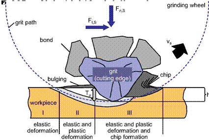
In the case of some grinding, honing and free abrasive grinding operations with bonded grains, cutting edge engagement is also force-bound. It is hereby often the case that the grain remains relatively fixed and penetrates into the workpiece at a predetermined path by the relative movement between the tool and the workpiece (Fig. 2.6). Cutting edge engagement is thereby conditionally track-bound. This working principle can be found with most machining methods with geometrically undefined cutting edges. It is based on the following observation on the engagement of individual grits.
During a machining process with a track-bound cutting edge engagement, the cutting edge of the grain penetrates the workpiece upon a flat path and, after a phase of elastic deformation, triggers plastic flow of the workpiece material (Fig.
2- 6). Because of the form of the cutting edge, the angle between the cutting edge contour and the workpiece surface is very small at first, so that no chips are formed initially. The workpiece material is merely shifted to the side, forming elevations and/or flows beneath the cutting edge to its flank face.
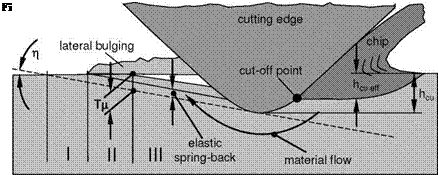
Only when the cutting edge has penetrated deeply enough into the workpiece that chip thickness hcu corresponds to the grain cutting depth Тц does actual chip formation begin [LORT75, MASS52, STEF78]. Since, as the sequence continues, deformation processes and chip formation appear simultaneously, it is decisive for the efficacy of material removal just how much of the chip thickness hcu is actually produced as chips and thus how large the effective chip thickness hcu eff is (Fig. 26).
Chip formation and thus hcu eff and Тц are influenced to a large degree by the friction conditions at the cutting edge. For a better understanding of the influence of friction in cutting edge engagement, it is useful first to explain the differences in chip formation with cooling lubrication with oil or emulsions. Fig. 2-7 illustrates the influence of friction on the grain cutting depth and the efficiency of material removal. With increasing lubrication, the grain cutting depth increases, and there is a longer lasting and therefore also stronger plastic material deformation [VITS85].
Increased lubricating capability of the cooling lubricant reduces the efficiency of material removal. At equal undeformed chip thickness h and less friction, a thinner chip (lower hcu eff) results, with which the ratio of chipped to deformed material volumes decreases.
Investigations have shown that, besides friction, the following quantities influence the amounts of hcu eff and Тц:
• the cutting edge radius ps,
• effective cutting speed angle n,
• cutting speed vc
• the flow properties of the material.
Usually, blunt cutting edges with a small sharpness parameter and a small angle П tend to promote deformation of the material, leading to larger grain cutting depths and thus to smaller effective chip thickness. With rising machining temperatures, the grain cutting depth increases, since the material becomes more ductile because of the higher temperature. With higher material malleability, the grain cutting depth decreases, since strain hardening has the strongest effect here. The capability of the material to flow beneath the cutting edge is determined by friction: at higher levels of friction, the grain cutting depth decreases.
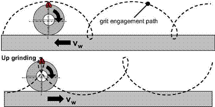
In considering the entire process, the speed of the grinding wheel should always be seen in relation to the workpiece speed. The cutting speed vc is defined as the vector sum of the grinding wheel peripheral speed vs and the workpiece speed vw. If we consider a cutting edge as a fixed point on the grinding wheel and describe its trajectory curve, cycloidal trajectories appear for both down and up dressing with varying markedness [EICH97, HARB96, SAWL64]. The kinematic roughness in the grinding direction is thus the result of the engagement paths of the grit, as is depicted for flat grinding in Fig. 2-8.

 |
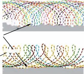 grit engagement paths in down grinding
kinematic roughness
‘ О hV •
grit engagement paths in down grinding
workpiece
Fig. 2-8. Cycloidal trajectories of an abrasive grain in down and up grinding

