In order to form a chip, the grains cutting into the component must be harder than the material which is to be machined. Crystalline and brittle abrasive materials are used. The grains splinter during the crushing caused by the production process, so that the fragments possess an irregular form with more or less sharp corners and edges. Natural or synthetic abrasive materials that already have the desired form in their raw state are also used.
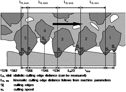
Fig. 2-2. Statistic and kinematic cutting edges
The grains protrude variably far from the bond material of the grinding wheel, thereby engaging with varying strength. Only especially protruding grains or parts of the grain surface penetrate into the component during the machining process, causing material removal. These are called kinematic cutting edges. The concept of static cutting edges is used when cutting edge distribution on the component is described without consideration of the machining process. This is shown in Fig. 22 [PEKL57, PEKL58].
Because of the large number of cutting edges, a metrological ascertainment of the geometry of all individual cutting edges of a tool is only possible at high efforts. Due to wear, the number of cutting edges and their geometry change constantly during removal. We can get an idea of the form of the cutting edges statistically by means of a cutting edge profile, which can then describe on average the
 |
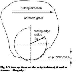
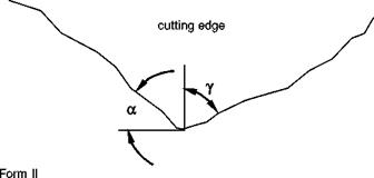
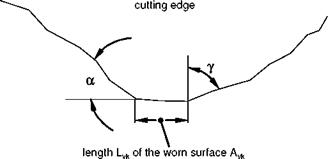
form of a cutting edge. In Figs. 2-3 and 2-4, two characteristic cutting edge profiles are illustrated, acquired by scanning the grinding wheel [GUEH67, STEF78]. To scan the grinding wheel topography, tactile or optical scanning systems are used primarily [GOSE89, POPP91]. Clearance angles are usually ignored in the determination of grinding wheel topology.
If the average profile of the cutting edges is approximated by a circle of radius ps (Fig. 2-3) [LORT75, MASS52], we can then define a sharpness parameter with the quotient from the chip thickness hcu and the cutting edge radius ps:
The sharpness parameter S of machining process with geometrically undefined cutting edges is remarkable under 1, whereas it is several orders of magnitude above 1 in machining processes with defined cutting edges such as turning.
Other typical cutting edge profiles are shown in Fig. 2-4. Individual abrasive grains can splinter during the production process such that its form can be described similarly to tools with defined cutting edges. A tip, the geometry of which should be determined as in Fig. 2-4 by the tool orthogonal rake angle y, the tool orthogonal clearance angle a and the wear surface Avk, should thus have a negative tool orthogonal rake angle in order to be comparable to the geometry of the grits. Many researchers are of the opinion that the average grit resembles a tip of a rake angle of up to у = -80° [GUEH67, WERN71].
Beyond this, two basic forms are distinguished in Fig. 2-4. Form I shows a cutting edge geometry devoid of wear. Form II illustrates a cutting edge contour with wear surface Avk, which can be considered as part of a flank face, so that the friction conditions are comparable with those of the flank face friction of a turning tool.
cutting direction
|
Form I
|
|
by abrasion or dressing Fig. 2-4. Description of an average grit profile in analogy to cutting edges used in defined machining |


