
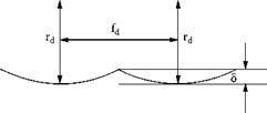
The resulting roughness is governed, in simplistic terms, by the height of profile S resulting from the overlap of the tool radius from one rotation of the wheel to the next. This height should always be less than the dress depth in order to avoid noncleanup of the wheel surface at each pass and a resulting poor appearance in the ground part. The value for S is controlled by the traverse rate, depth of cut, and tool radius. Significant research has been carried out to predict surface topography from tool profiles and wheel/tool interaction kinetics (e. g., Torrance and Badger [2000]).
7.2.6 Dressing Feed and Overlap Ratio
Grinding engineers employ empirical approximations and guidelines to determine dressing feedrate. Depending on the dressing depth, the tool is assigned an effective cutting width, bd, which is assumed is swept out on the wheel each revolution. An overlap ratio, Ud, is then assigned for each type of operation and allows the axial dressing feedrate, vfd, to be determined.
Ud = bd/f d = bi-nJvfi
For typical single-point dressing, dressing width, bd, is about 0.5 to 1.0 mm and the following values for overlap ratio, Ud, may be used for general applications. These values are applicable to all traverse dressing operations.
 |
Rough grinding Ud = 2-3 Medium grinding Ud = 3-4 Finish grinding Ud = 6-8
|
TABLE 7.2 Grit Size Values for Calculating Dress Traverse Rates
|
In practice, many problems are caused by setting the dressing feedrate too slow. This is equivalent to assigning a value of overlap ratio that is far too high. The result is rapid wear of the diamond and damage to the abrasive grains in the wheel. The grinding forces will be too high and the wheel will soon need redressing.
An alternative method, since the grinding severity is based on grit size in the wheel, is to set the effective contact width/rev to half the average abrasive grit size (Table 7.1).