
Nevertheless, the design still has problems with bore expansion albeit now directed to a movement on a keyed tapered arbor. For the very highest wheel speeds, OEMs and wheel makers are designing
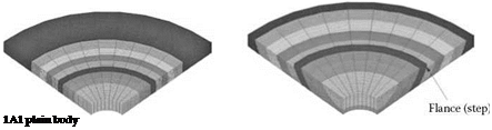 |
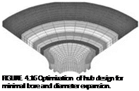
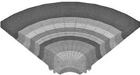
1-pc integral hub, plain body 1-pc integral hub, turbine body profile
 |
 |
wheels to bolt directly to the motor spindle. Several examples for both vitrified and plated CBN wheels are shown later.
 |
Figure 4.18 shows a typical steel-cored wheel for grinding camshafts at speeds up to 160 m/s. This particular example was made by TVMK for operation on a TMW camlobe grinder. The wheel has a small 40-mm hole governed partly by the motor spindle shaft size, but also allows a bore tolerance of ±2.5 pm to be practically achieved. There are a large number of bolts (10) to hold the wheel thus allowing a high clamping force to be achieved. Since the wheel face is flat and flush to the spindle there is no flange distortion. The bolt circle diameter is also small (68 mm), which minimizes problems from motor surge leading to slippage during start-up. The body is twice as wide as the CBN section and tapered down toward the outer diameter. This reduces the bore
|
FIGURE 4.18 Steel-cored vitrified CBN wheel for grinding camshafts at 160 m/s. |
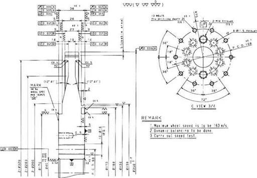
expansion without creating some of the stress distortions seen with the 3A1 shape above. The vitrified CBN layer depth is 5 mm with a total layer of abrasive of about 6.5 mm.