
Fm = Ms g/
4.6.3.1
 |
Clamping Force for Unbalance of the Wheel
Fu = 8 Vs2 /rs2 Vb
where
8 = unbalance (force. distance) vs = wheel speed rs = wheel radius
4.6.3.2 Clamping Force for Motor Power Surge
It is assumed that electric motors can develop a surge torque of 2.5 times their rated torque before stalling.
Fs = 25Psp rf /vs Pb rs
where
rf = flange average radius Psp = spindle motor power
4.6.3.3 Clamping Force for Reaction of Wheel to Workpiece
Again assume a motor surge capability of 2.5:
Fn = 2.5Psp/Vs pb Pg
 |
 |
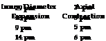 |
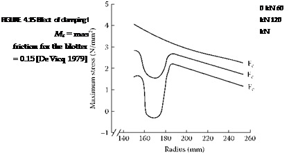
Dimensional Changes in a High-Speed Rotating Steel Cored Wheel
where
= coefficient of grinding (0.4 typical)
In addition to these forces there will be effects of accidental vibration and shocks, possible compression of the blotters, and the increased clamping force required as the wheel wears when holding constant surface footage. Practical experience leads to another factor 2 on forces. Total clamping force required becomes
When the number of bolts is known, tables are available giving torque/load values for the required clamping force. Calculations then need to be made to determine the flange deflection.