
Holding the abrasive section together on the wheel body has already been discussed. A second problem is how to hold the wheel body on the machine spindle.
 |
 |
 |
Centrifugal forces cause the wheel to expand radially both on the outer diameter and the bore. It, therefore, must also contract axially. The problem is, therefore, to prevent movement of the wheel on the hub either by minimizing bore expansion/contraction and/or by maintaining sufficient clamping pressure on the wheel to resist torsional slippage.
1.5.1 A Conventional Wheel Mount
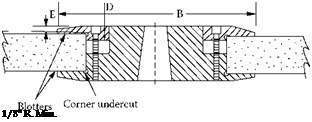
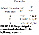
An example of a conventional wheel mount [ANSI B7.1 1988, Figure 43] is shown in Figure 4.14. 4.6.2 Use of Blotters
Blotters are required for conventional wheels to equalize the variations in pressure due to the effects of microasperities in the grit structure of the vitrified body. Failure to incorporate compressible blotters gives rise to local stress concentrations that are very dangerous. The blotters are made of either paper or plastic (polyester) with a thickness of typically 0.015 in.
4.6.3 Clamping Forces
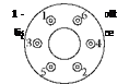
The flanges are fixed together with a series of bolts, six in the example above, that are torqued to <20 ft. lb in the sequence shown unless otherwise recommended. Overall clamping pressures must to be kept to <1000 psi and usually are considerably below this value.
Optimum torque values can lead to lower rotational stresses and higher burst speeds. Barlow et al. [1995] carried out FEA analysis of clamping pressures and the effect on wheel stresses. An example showing the reduction in maximum radial stress is shown in Figure 4.15.
However, overtorquing causes distortion of the flange leading to a high-stress peak that can readily exceed 2000 psi and lead to wheel failure [Meyer 1996]. De Vicq [1979] recommended using tapered flange contact faces to compensate. Unfortunately, this is impractical except for dedicated machines and the accuracy of torquing methods is not always sufficient to ensure correct flange deflection.
In the absence of any significant axial contraction, it is relatively straightforward to calculate clamping forces required to prevent rotational slippage [Menard 1983].