
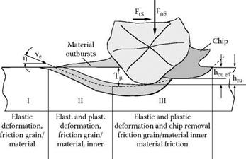
During grinding, the cutting edge of the grain penetrates the workpiece on a very flat path causing plastic flow of the material after a very short phase of elastic deformation. Since the angle between cutting edge contour and workpiece surface is very small due to the cutting edge rounding, no chip is formed initially. The workpiece material is only thrust aside, forms material outbursts or side ridges, and flows to the flank underneath the cutting edge [Koenig and Klocke 1996]. Figure 3.8 shows the chip formation during grinding of ductile materials.
Only if the cutting edge penetrates the workpiece to a depth that the undeformed chip thickness, hcu, equals the so-called critical cutting depth, T^, does the actual chip formation begin. Since displacement processes and chip formation occur simultaneously in the further process, it is crucial for the efficiency of the material removal how much of the uncut chip thickness, hcu, is actually removed as chip, and what the effective chip thickness, hcueJj, is.
Grof [1977] has further differentiated the chip formation process during the machining of ductile materials with high cutting velocities. On the basis of experiments, he determined altogether six phases of singular chip formation during grinding (Figure 3.9). In the first quarter of the contact length (phase 1), the engaging abrasive grain first makes a groove, causing plastic and elastic deformation in the material, which is then thrust aside from the groove. The surface is presumed to consolidate during this contact phase [Werner 1971] without chip formation.
Through the further advance of the cutting edge (phase 2), a flow chip is removed with a nearly parallelogram-shaped cross section. This chip is compressed and bent in dependence of the pore space. Due to the large point angle of a cutting edge, the chip is very flat and offers a big surface for heat discharge through radiation and convection. In case of small infeeds or feeds, the working contact ends in the third phase, forming almost exclusively thread-shaped chips.
In case of large infeeds and feeds, the cutting edge penetrates the material deeper. This leads to a distinctive shear zone at approximately three fourths of the maximum engagement length resulting in strong heat development (phase 3). The strong material accumulation through the high pressure causes an increase of the contact zone temperature. Due to the small effective surface of the cooling lubricant, this heat cannot be discharged. This leads to a melting of the formed chip above the plastic state.
|
|
|
FIGURE 3.9 Removal process during the machining with high cutting speeds. (From Grof 1977. With permission.) |
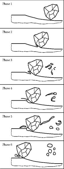
If the cutting edge engagement is terminated in this phase, tadpole-shaped chips are formed (phase 4). If the engagement takes place along the entire contact length, the whole material is liquefied in the pore space after the thread-shaped chip falls off (phase 5).
Due to the surface tension, the molten chip becomes spherical after leaving the contact surface. This takes place in a zone where there is none or only a small amount of cooling lubricant (phase 6). The fact of sphere formation has been observed by other researchers as well [Hughes 1974, Marinescu et al. 2004].
A further model of cutting edge engagement has been presented by Stephens [1983]. The cutting edge engagement can be ideally considered as an even-yielding process. In this model, the contact zone is divided into layers that are arranged parallel to the movement axis. The material starts
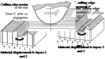 |
FIGURE 3.10 Idealization of the cutting edge engagement through plain yielding. (From Steffens 1983. With permission.)
to yield in different directions at the cutting edge engagement. Thus, the individual layers are thrust aside at the point of engagement of the first cutting edge. When successive cutting edges engage, these areas are removed or thrust aside anew. Through these processes, the number of kinematic cutting edges increases partially in a subarea. Since these changes are statistically distributed to the whole surface, there is overall no material accumulation.
The description shown in Figure 3.10 can serve as a model for the alternative description of a layer as an interaction of all displacement processes. A further prerequisite for the application of slip line theory is the knowledge of the rheological properties of the material, which is supposed to be inelastic ideal plastic.
On the basis of these theoretical considerations and experimental investigations, statements can be made on the friction conditions, which are decisively influenced by the lubrication [Koenig, Steffens, and Yegenoglu 1981, Steffens 1983, Vits 1985]. If the friction is increased, the critical cutting depth decreases, which is additionally influenced by the radius of the cutting edge of the
grain [Koenig et al. 1981, Steffens 1983]. Improved lubrication increases the plastic deformation toward a higher critical cutting depth. Thus, there is a reduction of friction between the active partners. With constant uncut chip thickness, hcu, the effective chip thickness, hcueff (thickness of the formed chip), decreases simultaneously with a reduction of friction [Steffens 1983, Vits 1985].