
In order to compare a variety of grinding processes, it is necessary to define general and comparable process parameters. With these parameters, different processes can be compared with each other allowing an efficient optimization of the process. The most important grinding parameters are the geometric contact length, lg, chip length, lcu, and the chip thickness, hcu.
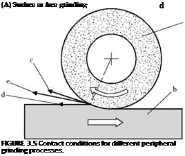
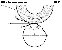
The kinematics and the contact conditions of different grinding processes are represented in Figure 3.5. They constitute the basis of many process parameters.
Neglecting the elastic deformation of the active partners of the grinding process, the grinding wheel penetrates the workpiece with the real depth of cut, ae. The arc contact length is defined by the geometric contact length, lg:
![]()
![]()
![]() (3.1)
(3.1)
For the same depth of cut values, different contact lengths result in the case of cylindrical and surface grinding. The equivalent wheel diameter deq is a calculation method of representing geometric contact length independent of the grinding process, where
 |
 |
applies to the equivalent grinding wheel diameter in external cylindrical grinding. In the case of internal cylindrical grinding, the equivalent grinding wheel diameter is:
(a) Grinding wheel, (b) Workpiece, (c) Cutting speed, (d) Feed speed, (e) Resulting effective speed
The equivalent grinding wheel diameter deq indicates the diameter of the grinding wheel, which has the same contact length in surface grinding. Thus, the equivalent grinding wheel diameter corresponds to the actual grinding wheel diameter in surface grinding.
The movement of the wheel relative to the workpiece is put in related to the speed quotient q. In
up-grinding, it is negative: In peripheral grinding with rotating grinding tools, the cutting edges move on orthocycloidal paths due to the interference of the speed components.
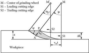
Figure 3.6 demonstrates the paths of two successive cutting edges. Both points have the same radial distance from the wheel center. The path the center travels between the two engagements of the wheel results from the feed movement and the time required.
The cutting edge engagement and the resulting uncut chip parameters depend on the statistical average of the cutting edges distributed on the grinding tool. The equation
![]()

 |
(3.5)
relates the maximum uncut chip thickness hcu to the cutting edge distribution, the grinding parameters, and the geometric values [Kassen 1969]. The mean maximum uncut chip cross-sectional area Qmax is a further characteristic parameter of the grinding process. Like the maximum uncut chip thickness hcu, it depends on the parameters, the cutting edge distribution, and the geometry of the active partners of the grinding process. The mean maximum uncut chip cross-sectional area Qmax is calculated from
On the basis of these values, a theoretical assessment can be made of the grinding process. There is a direct relation between the cutting parameters and the resulting surface quality. Equations (3.5) and (3.6) lead to the conclusion that the surface quality improves with increasing cutting velocity and grinding wheel diameter. With increasing feed speed and higher depth of cut, however, the surface quality decreases.
The value of the uncut chip parameters, however, are only applicable to a real grinding process to a limited extent, since the kinematic relations were only derived for idealized engagement conditions [Marinescu et al. 2004]. The cutting process is not a simple geometric process; there are also plastic and elastoplastic processes in real grinding so that chip formation is different from the geometric theory. It is for this reason that experiments are indispensable to gain knowledge and understanding about the material removal mechanisms.