
 |
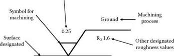
Common roughness specifications (marks) on part drawings are shown in Figure 2.7. This gives both the current standard practice, especially in Europe, and the older machining marks still seen
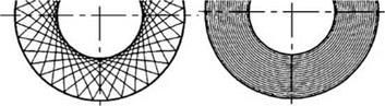
Cross-hatch grind pattern from a Concentric rings grind pattern from a face grind operation, e. g., shoulder plunge or angle approach shoulder kiss or double disc grind grind with line contact
(a) (b)
|
Part print finish markings Roughness Ra (pm)
Machining marks approximate values (common on Japanese prints) |
V 25 Ra (pm)
V V 3.2 Ra (pm)
V V V 0.8 Ra (pm)
V V V V <0.16 Ra (pm)
FIGURE 2.7 Print markings for surface finish.
especially on Japanese drawings. One (V) or two (V) marks are indicative of a turning or milling operation, but three (V) or four (V) marks are indicative of the requirement to grind or even lap.
Two other force-related factors are of particular interest to end users with low stiffness systems such as internal grinding. The first is stock removal parameter Л.
2.2.21 Stock Removal Parameter
Л is defined as the ratio between stock removal rate and normal force:
Л is an indicator of the sharpness of the wheel, but is limited by the fact that it must be defined for each wheel speed and removal rate. The second factor is decay constant t.