
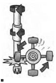
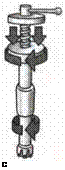
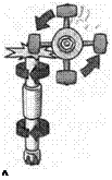
By 1900, rock drilling had reached the point at which hammer drills were available that operated at several hundred cycles per minute, worked at any angle of inclination, had the cutting head held at the rock face by an air cylinder, and had the chips and fine detritus continually removed from the working zone by air or water.
Compressed air was being used to power the drills because it was an inexpensive and efficient method of transferring energy over long distances or to difficult sites, such as underground. But there were some problems:
■ Machines were heavy and had to be fixed in place with the main support being wedged between the floor and the roof. Two men were required for each machine.
■ The dust created by drilling was a health hazard. This could be reduced but not eliminated by the water used to flush away the cuttings.
■ The cutting heads that were part of the drill rods lasted only about 0.5-1.0 m in hard rock and up to 3 m in softer rock before requiring sharpening.
Keeping the drills sharp meant there was a constant flow of drill rods between the mining face, the cage in which equipment was transported up and down the shaft, and the drill shop that was always built on the surface close to the shaft to reduce the travel time. At one gold mine in Canada at which 1,500 tph of very hard rock were mined, 34,000 drill steels were sharpened each month (Fisher 1937), and many men were employed to work on sharpening and transporting drill rods. In some mines the forged cutting end of the drill rod was replaced by a detachable bit, but this was not always a success because of breakage problems at the connection point, which was inherently weak. The bit could also wind off the rod and be lost.
Much effort went into building light, hand-held drills that had become available by 1912. These had a profound effect on drilling because they made the work of the driller underground much easier and eventually eliminated the heavy tripod mountings that were so difficult to transport and erect.
Before the 1950s, drilling underground was usually performed with one-piece drill steels and relatively small percussion drills. These steels were commonly used in batches of increasing length and decreasing bit diameter to drill holes of 6 m or less. An early improvement was the development of tungsten carbide bit inserts that greatly reduced the rate of bit blunting. Tungsten carbide was made in Germany in the late 1920s, and cemented carbide bits, in which pieces of tungsten carbide were embedded in steel, were made in Sweden in the early 1940s, mainly for use in civil engineering projects. They were introduced into the mining industry in the 1950s. Detachable tungsten carbide bits and coupled rods permitted the drilling of 20 m long holes because the size of the drill drive no longer limited the length of the drill rod. Larger percussion drills were produced with new rod feeding and handling systems, and over this development period blast-hole diameters increased from 30 to 75 mm.
An inherent shortcoming of the coupled rod percussion drill system was the flexibility and discontinuity of the drill string. This led to bending of the blast hole, which increased exponentially with depth and caused erratic and unpredictable spacing of the hole toes, unevenness in charging density, and poor fragmentation. Consequently, blast hole length was limited to 25-30 m. Another shortcoming was the loss of hammer energy between the out-of-hole drill and the bit, again due to drill string flexibility and looseness of the drill string in the hole and of coupling threads.
In the 1970s, in-the-hole hammer drills and rotary drills were introduced to large underground mines. With in-the-hole hammers, percussion is delivered directly to the bit and less energy is wasted in the drill string (Figure 10.3); with rotary drills, large-diameter,
 |
 |
 |
smoothly coupled drill strings are used that fit neatly into the blast holes and hole deviation is greatly decreased.
The result of these developments was that drill holes increased from 57 mm in diameter and 1-2 m long in the 1960s to 150 mm in diameter and 30 m long in the 1980s. The main objective in introducing these large blast holes was to permit use of longer holes and to increase sub-level spacing (a system of horizontal underground workings from which ore is mined). To achieve uniform ring charging density the spacing between blast hole toes had to be widened accordingly.
Unlike in open cuts where bench drilling permits the use of parallel blast holes, underground limitations usually require the use of ring patterns, which are far from ideal for even distribution of explosives. Drill holes in ring patterns underground also require collars to be uncharged, thereby wasting portions of drill holes. By the late 1980s, sublevel spacing of 50-60 m became possible, which allowed larger blasts and more efficient blasting, but even in the 1980s drill holes deviated considerably from plan. This meant that not all the explosive was placed according to the blast design.
In the 1990s, advances in mechanical and materials engineering, electronics, and computer systems made drilling machines more durable and more reliable in terms of drilling to plan. Straighter drilling has been achieved by the use of tube drilling and guide tubes, more rigid drilling rigs, more accurate (computer-controlled) initial alignment of the drilling machine, and down-hole hammers. TV cameras and survey instruments provide details of where the holes went. Drill holes still deviate but their accuracy is good enough to be able to investigate and understand the effect of drill-hole variables on blast results.