
First Generation Dynamic air separators have several common characteristics:
■ Internal rotors that are also feed distribution plates
■ Airflows generated by internal or external fans
■ Collision blades that interrupt the flow and rejection of coarse particles
FIGURE 9.11 Alpine Zig Zag classifier FIGURE 9.12 Askham air separator (Butler
showing the passages and collision surfaces 1913)
(Klumpar, Currier, and Ring 1986; reprinted by permission from Chemical Engineering)
Dynamic separators started with the Askham air separator, which became known as the first-generation air separators, and its principle of operation, which is the basis of modern air separators, is shown in Figure 9.12. D. Butler (1913) described the operation of this machine:
The machine consists of a funnel-shaped casing, within which is a second funnel with an annular space between the two. As its name suggests the separation is effected by a current of air which is produced by a fan of special design FF revolving in the upper or cylindrical part of the casing. The cement is fed into the cone G and falling onto the rotating disk E is thrown in a thin stream all round towards the fixed hood D. The current induced by the fan passes upwards and outwards between the fan blades carrying with it the finer particles which are thrown into
the outer casing A and fall out the bottom for conveyance to the warehouse. The coarse particles which are too heavy to be lifted by the current of air fall into the casing B whence they return by the branch pipes aa to the mills for further reduction. The current of air returns through the opening o.
The Sturtevant Whirlwind classifier, shown in Figure 9.13, was a popular first — generation classifier that was similar to the Askham classifier, although it had an additional auxiliary fan on the same shaft as the main fan. This created turbulence and assisted classification. Eventually the auxiliary fan had a separate variable-speed drive, which gave some control over the cut size.
The main advantages of the first-generation classifiers were good classification of very fine products on an industrial scale that had not previously been possible and relatively low capital costs. The main problems were
■ Fine particles were not removed from the recycling air, and they accumulated in the coarse product, leading to a high recycle of finished product to the mill.
■ The circulating air became very hot (>120°C), which is unsuitable for cement clinker circuits in which the gypsum could be affected. First-generation units have been preferred for circuits grinding raw materials for processing in the kiln.
■ The sizing distribution and surface area of the fine product were difficult to change, although this problem was reduced when the auxiliary fan with the separate variable-speed drive was used.
■ The distribution of feed on the disk and dispersion in the air were uneven, and this exacerbated the problem of high recycle.
For 75 years, this type of classifier was used in cement plants, and many are still in use today. The demand for more cement increased rapidly in the 1950s and there was a need to improve cement quality, which meant closer control over size distribution. The deficiencies of the first-generation air classifier had to be corrected, and this resulted in the design of the second generation of dynamic classifiers, which are discussed in the next section.
Second Generation First-generation separators suffered from high bypass, and it was difficult to change the sizing distribution and surface area of the fine product. In the 1950s, these problems outweighed the advantage of relatively low capital cost and had to be fixed. One solution was to remove the fines from the circulating air, and this led to a second-generation separator becoming available in 1960. Its main features were
■ An external fan to circulate the air, which replaced the internal fan
■ Several external planetary cyclones, which replaced the fines cone
■ Independent control of the separator speed and air circulation
The air containing the fines went from the classifier to the cyclone where the solids were removed through the apex, and then to the fan that recycled it back to the classifier. The difference in operation of a first-generation Sturtevant Whirlwind air classifier and a second-generation Humboldt Wedag air classifier can be seen in Figure 9.13. The main advantages of the second-generation air classifier were better removal of the fines, sharper separation, lower bypass, and continuous control of the fineness. The main disadvantages were their large size, incomplete dispersion of the feed and removal of the fines from the recycling air, and a rather erratic cut size. For a few years after they came on the market, they were preferred to the first-generation units but they had a relatively short life because of their size and were replaced by the more compact third-generation unit.
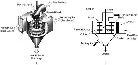
Third Generation In the 1970s, a new dynamic, high-efficiency separator was designed with the objectives of decreasing bypass, giving a better precision of separation, and decreasing cut size (Onuma and Furukawa 1984). The O’Sepa separator was the first of the third generation, and it quickly proved its value when it was installed in a plant in 1979 (see Figure 9.14). Some improvements over previous models were
■ The air entered the classifier horizontally and had a uniform velocity across the flow.
■ The distribution plate was at the top of the airflow, and the feed fell as a well — dispersed curtain of particles.
■ Particles passed through a rotating cage before entering the fine stream, and the collision of the particles with the bars of the cage assisted in rejecting the coarser particles from the flowing air.
■ The product size could be adjusted online by changing the rotor speed.
■ The dust-laden air from the mill was used as classifying air without impairing the classification efficiency, because the air left the separator and the fines were removed before it was recycled.
In operation the air passes through the stationary guide vanes, and the feed material is dispersed in the annular gap between these and the rotor. After passing through the vanes, the air moves in a horizontal vortex. The air carries the fine material tangentially across the face of the rotor that is turning in the same direction as the vortex. The coarse particles are separated by a combination of gravity, centrifugal, and impact forces and fall into the collecting cone at the base. The fine particles are conveyed to a dust collector. Their sharp classification and low bypass reduced the circulating load in tube mill-separator circuits and allowed an increase in feed rate by 20%-40%. The energy consumption per ton of cement was reduced by 15%-35%.
The principles involved in the O’Sepa third-generation or high-efficiency separator have been widely adopted by other manufacturers which have built particular features into their machines. The high-efficiency separators have replaced conventional separators
|
FIGURE 9.14 O’Sepa separator: (a) pictorial view (Fuller Company 2001; reprinted by permission from F. L. Smidth) (b) method of operation (Klumpar, Currier, and Ring 1986; reprinted by permission from Chemical Engineering) |
in the housing of vertical roller mills and have reduced considerably the mass of rejects returning to the grinding table.
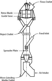
The Sepax separator is a high-efficiency separator which can deliver conventional fines and reject, along with very coarse or heavy particles (Figure 9.15).
The original Sepax separator (Figure 9.15a) was designed to work with air-swept ball mills with the feed that is the mill product already suspended in air when it enters the separator. Additional air enters the separator at its base, and classification occurs on the heavier particles that enter the bottom zone. The coarse reject, including steel from the mill, falls through the rising air and is removed at the base. Fine particles from the bottom zone and ball mill discharge are swept by air into the upper section of the unit where they are classified in a high-efficiency separator. The coarse particles from this separator are returned to the mill via an outlet above the bottom separator.
When HPGRs were used for grinding fresh clinker before it entered the tube mill, it became apparent that the grit separator in the base of the Sepax unit could be operated in closed circuit with the rolls to return coarse flakes to the rolls and send the fines to the high-efficiency separator for the production of finished cement. Figure 9.15b shows a Sepax unit with the base modified so that it contains the following:
■ A feed inlet for the flakes discharged from the rolls and a deagglomerator rotor to break up the flakes
■ An outlet for the grit (in this case the coarse product from the first separator) to be returned to the rolls
■ A spiral inlet for the air
In all high-efficiency separators, the product can be controlled with the rotor speed or airflow although in practice the airflow is seldom changed.
Ultrafine particles have become essential in many industries, and it has been necessary to make classifiers that can separate at sizes of less than 10 |im, often much less. These cuts have been obtained by small, high-speed rotating cages that work in a similar manner to the rotating cages in the high-efficiency separators. This type of classifier will become more important as the demand for ever-finer particles increases.
 |
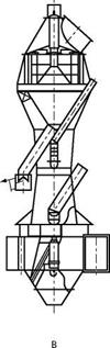 |
FIGURE 9.15 Sepax two-stage high-efficiency separator: (a) original unit with a single-feed entry, which is the tube mill product (b) modified for use with roller press product so that it has feed entries for the roller press and tube mill products (Smidth 2000)