
Many roller mills were sold from 1930 to 1950, but there was little enthusiasm for new designs because of the economic depression and World War II. The revival of industry after the war increased the demand for materials, and new mills were required with grinding chambers that had higher processing capacities.
Fixed Rollers and a Spinning Bowl
By 1925, Loesche’s experience with the Maxecon and Raymond mills persuaded him that fixed rollers and a spinning bowl was better than spinning rollers and a fixed bowl, which was the mechanism in the Raymond mill. With this reverse design the rollers could be spring-loaded and higher grinding forces could be applied than those generated by the centrifugal forces in the Raymond mill. With the fixed roller-spinning bowl system
the material was fed into the center of the bowl, flowed toward the wall by centrifugal action, and ground by passing between the rollers and the bowl wall. Loesche’s first mill using a spinning bowl was named the Maximal mill (see Figure 6.12).
There was still the problem of geometry. The rollers rotated in a horizontal plane and had to fit inside the wall of the bowl, and this gave little scope to increase the roller diameter and mill capacity. The solution was to incline the wall of the bowl backward so that the roller axles were at a 45-degree angle that removed the restriction on roll diameters. The angle of inclination of the axles was reduced in stages and reached 15 degrees by 1935, which is the current value for Loesche mills. The first of these mills, built in 1928, had backward-sloping bowl walls and the rollers were held in rocker arms. The new mill was offered to BEWAG, which accepted the machine on condition that it would be called the Loesche mill. This condition was intended to make it absolutely clear that if the mill failed, the inventor of the mill carrying his name was responsible for the functioning of the machine and not the BEWAG department dealing with new construction (Brundiek 1989). In the early air-swept roller mills, efficient classification was necessary, and static centrifugal classifiers were used but were soon replaced by dynamic classifiers to give better control of particle size. By 1937, 400 mills had been sold, and the mills remained as popular as the difficult circumstances permitted from 1937 to 1952. The largest Loesche mill available during this time was 2 m in diameter, and the grinding elements were two 1.5-m diameter rollers. It was used for grinding cement raw materials at 50 tph.
Early in the 1960s, dry grinding replaced wet grinding ahead of the cement kiln, and roller mills were used for grinding limestone. The largest mill available then could grind 120 tph of limestone-large enough to produce 1,500 tpd of cement clinker, which was
|
FIGURE 6.13 Positions of roller mounted on pedestal in Loesche roller mill: (a) operating position (b) start (clear of bowl) (c) service (swung away from bowl) (Brundiek 1989; reprinted by permission from Loesche) |
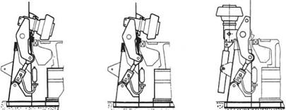
the maximum capacity of cement kilns. By 1970, better kiln technology had increased kiln capacity to 3,000 tpd, and mills had to be built to grind 240 tph of limestone. Making larger rollers was not a problem, but holding them in position against the spinning bowl while they were grinding and raising and lowering them easily at other times was more difficult. To do this, a module system was designed that comprised a roller, rocker arm, and spring-loading system mounted on an individual pedestal. The operation of this module is shown in Figure 6.13.
This development opened the door to designing very large roller mills, because huge rollers could be installed in a machine and handled easily in operation. In 1999, a 750-tph mill that had four wide rollers 2.7 m in diameter by 0.9 m long was installed at the Siam Cement Company’s Thung Song plant in Thailand. This mill was driven by a 5,400-kW motor (Ongtkoon 2000; see Figure 6.14).
There are always many engineering problems involved in building and assembling very large grinding mills; for example, the grinding table in the Thung Song mill weighed 230 tons and had to be cast in one piece.
The advantage of roller mills was that they required less energy per ton than ball mills to grind limestone to the same size. Clinker grinding is the high-energy consumer in cement plants, and this pointed toward using a roller mill for grinding cement clinker to finished cement. The problem was that a bed of cement particles on the grinding table was unstable, because (1) it was very fine, containing up to 10 times the volume of classifier reject as of new feed, and (2) it contained occluded air.
Aerated fine particles flow quickly across the table and are not ground efficiently. The method adopted to improve the stability of the bed was to add a small roller (“S-roller”) ahead of each main roller (“M-roller”). The S-rollers were set well above the bed and prepared it for the M-rollers by consolidating and partly de-aerating the bed (see Figure 6.15). These mills are now used for producing finished cement.