Chattering represents one of the main causes of quality problems in grinding, because the dimension and shape accuracy as well as the surface quality are influenced negatively [BAUS03, KARP01]. Chattering can be traced back to selfexcitation.
In the grinding process, the main causes of forced vibrations are primarily imbalance and grinding wheel eccentricity. Further possible causes are disturbances induced through the foundation or generated in the hydraulic system of the machine.
Among self-excited vibrations, chattering represent the largest problem in the grinding process. The excitation mechanism of chatter vibrations can be derived primarily from the ambient noise of the cutting forces.
In the context of process monitoring, it is possible to recognise chattering by the amplitude or power spectrum of several process parameters, whereby the effective power signal is not capable for clatter recognition because of its inertia. On
the other hand, both in the spectrum of the normal force signal and in the spectra of the acceleration and AE signals, a clear peak forms as chatter vibrations emerges in the system frequency characteristic for chattering [BAUS03, INAS01, KOEN91].
Chattering can also be monitored by means of the dynamic portions of the AE — URMS signal [MEYE91]. In this case, the dynamics characteristic DAE serves for chattering detection.
10.6.2 Process Step Recognition as an Element of Reliable Monitoring
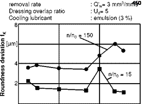
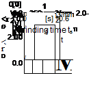
Besides determining the dynamics characteristic, it is possible to analyse the signal form of the AE-signal. Fig. 10-12 shows an example of this. The unstable conditions of the grinding wheel topography in this process led to clearly greater form deviation fk in comparison with the trend of the previous processes. As the representation of the associated process signal of the AE shows, the topography of the grinding wheel breaks down here after the first third of the roughing phase. New sharp cutting edges are engaged so that the URMS-value reduces abruptly. The determination of the stationary phases of the process detects this, in that the phase analysis indicates four process phases instead of the three phases expected. For purposes of comparison, the AE signal belonging to the following workpiece is also represented in the illustration. By identifying quasi-stable process times, step recognition thus provides a service life parameter that reacts sensitively to alterations in unsteady process components. The latter have an immediate effect on form deviations in the workpiece [KOEN91, MEYE91].

 |
 |
Fig. 10-12. Step recognition for identifying quasi-stable process phases.
