
After converting the acoustic emission conveyed by the machine components by means of the AE-sensor, further analysis is possible using an electrical AC signal. Bandwidth and frequency composition as well as the dynamics of the AE are modified by the path of transmittance and the sensor properties. Now we have a high-frequency, broadband, stochastic signal with determined quantities on hand, which must be conditioned for the determination of process-specific properties [MEYE91].
The signal is composed of parts which can be directly derived from the process as well as irrelevant, disturbing components that interfere with the useful signal during transmittal until exiting the sensor. The primary goal of signal evaluation is
thus clearly to increase the distance between the interference and useful signals by means of a suitable consolidation and selection of information. This is immediately linked to the extraction of characteristics, which must react to changing process conditions in a reproducible manner and with sufficient sensitivity.
In order to extract essential information from the AE signal, a modulation of amplitude is executed. For this purpose, the effective value of the signal is found for a determined frequency range. This can be achieved by means of a signal processing chain, consisting of a band-pass filter with which the frequency band of interest is selected, a detector and a low-pass filter located downstream thereof (Fig. 10-6). In this way, all essential information can be extracted from the high — frequency AE-signal. In the subsequent digital processing of First Contact Control
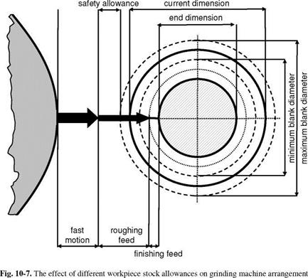
Besides the cutting ability of the grinding wheel, altered by the dressing and grinding processes, various properties of the blanks, above all varying workpiece allowances, cause changes in the cutting forces. Fig. 10-7 shows the geometrical conditions that exist when workpieces with fluctuating stock allowances are to be machined. In this case, by means of correspondingly large safety allowances, we should reach a condition in which the grinding wheel does not make contact with the workpiece during a rapid velocity even with the largest possible allowance. For small allowances however, the grinding wheel only gets in contact with the workpiece very late. On the one hand, a lot of time is therefore lost for so-called air grinding, on the other hand larger allowances lead to larger cutting forces and
system stresses than smaller allowances. In the latter case, the grinding cycles can be so short that even during the roughing period, a stationary material removal rate is not possible.
Fluctuations in material composition and structural formation in the workpiece’s surface layer also have an altering effect on the cutting forces. Due to the clamping device common in turning operations, the blank’s surface is mostly excentrical. This excentricity causes periodical changes in the cutting force during the grinding process. These changes result in roundness errors for small allowances in the finished part [KOEN89].
|
|
Since the selected safety allowance cannot be chosen arbitrarily small, we seek to pass through the air grinding path with increased feed velocity (air grinding feed velocity) and, shortly before or after the grinding wheel and the workpiece get in contact, to switch to roughing feed velocity. The position of this shift must be adjusted to the dimensions of the respective clamped workpiece. We can determine it with two fundamentally different sensor types, that is, with contact sensor systems or with approach sensor systems.
Contact sensor systems report the contact of the grinding wheel and workpiece in accordance with various operating principles (table 10-1). Also, they can respond with varying delay times according to the respective operating principle and the measuring devices used [ENGE77, FLAI80]. Since the switching times of the machine controls and drive system inertia must still be accounted for, grinding wheel and workpiece stress can increase significantly due to a high air grinding feed velocity.
|
Table 10-1. Measurement variables and reaction times of contact sensor systems.
|
The grinding wheel’s service life can be negatively influenced especially during a rapid approach of excentrical workpieces. If at the moment of contact that part of the workpiece circumference is turned to the grinding wheel which has the smallest distance from the centre line of the grain peaks, the momentary depth of cut increases and with it the specific material removal rate under further turning of the workpiece in excess of the maximum reliable value. This leads to an overloading of the workpiece and the grinding wheel surface.
As opposed to contact sensor systems, approach sensor systems relay information to the machine control about the relative position of the grinding wheel periphery and the diameter of the respective clamped blank, which is detected by the diameter measuring device, already before contact is made between the grinding wheel and the workpiece. These sensors thereby make it possible to pre-calculate the air grinding path, which can then be passed through at maximum speed [THYS75]. However, problems related to grinding excentrically clamped workpieces exist in this case too, since the contact arm of a diameter measuring device, which operates mostly series connected, determines the misalignment of the workpiece. Here too, unintentional collisions between the workpiece and the grinding wheel can thus occur.
Customarily, first contact sensor systems are utilised in contemporary grinding machines, which detect contact between the grinding wheel and the workpiece by means of acoustic emission (round/flat grinding) or by means of the effective power (internal cylindrical grinding). These systems approach with a positioning speed of usually three to four times of the feed velocity in roughing and switched to the roughing speed after getting in contact. Contact is recognised with the help of a static threshold that must exceed a programmed minimum time. The amount of this threshold depends primarily on the idle signal and the roughing signal measured in the process. For the acceleration sensors used in the majority of applications, a first contact threshold of 5 to 15 % of the roughing signal is chosen. Typical delay times range between 10 and 100 ms. Typical time constants т for the signal increase exhibit a range of т = 0.1 to 1 s for flat and external cylindrical grinding operations, while the unstable tools used in internal cylindrical grinding can lead to time constants of т = 10 to 20 s.