
 |
 |
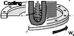
One cutting method that is still widespread today is inner diameter (ID) slicing. In this method, a rotating steel cutting blade serves as the tool. These are fastened at their outer diameters, similarly to the clamping mechanism used for drums. The actual cutting operation takes place in the centre of the saw blade, the inner diameter (Fig. 9-12). The inner diameter of the saw blade is galvanically coated with diamond particles. The cutting process is initiated by guiding the ingot to be cut through the inner diameter. Then, either the saw blade or the ingot is moved radially. The method’s kinematics thus corresponds to that of infeed grinding [BRIN87].
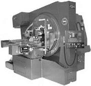
Fig. 9-12. left: principle sketch of the ID-technique; right: picture of an ID- separating machine, company Meyer + Burger AG
In the case of inner diameter slicing, wafers can only be cut one by one. The high cutting and feed velocities (vc = 25 m/s, vf = 50 mm/min) compensate for this
disadvantage to some extent. However, the productivity of a modern MWS machine cannot be realised. Due to the machine’s kinematics, the maximum ingot diameter is limited to 200 mm. In addition, the process is characterized by large cutting losses of ca. 330 qm per operation, which detracts from the cost effectiveness of the process. Furthermore, the method is limited to a minimal wafer thickness due to pronounced sub-surface damage of the crystals.
The advantage of this method compared with the MWS process lies in its flexibility. This predestines inner diameter slicing especially to those areas of substrate manufacture in which the number of pieces is smaller and the geometric shape of the wafer changes more frequently.
The demand for larger wafer geometries, thinner wafers and higher cost effectiveness often push this cutting technology to its limits, which is why it is often substituted with MWS technology.
![]()