
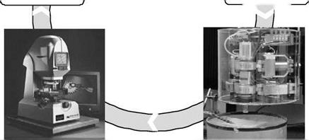
Three components are necessary for zonal polishing (Fig. 8-21):
• The use of a suitable measurement technique is necessary to measure the respective surface topography. The data are compared to the target geometry so the respective fault profile can be acquired. Interferometric methods find particularly broad use for the measurement of geometries.
• The measured fault profile is integrated into a removal model on the basis of which the path data and the residence time of the subsequent polishing step are calculated. The more accurate the removal model, the fewer iterative steps needed.
• The third component in this control system is the polishing machine. The machine must be able to execute the calculated track data as precisely as possible. In this process, the tool design is of decisive importance. In particular in the case of aspherical geometries or freeform surfaces, the tool must be adjustable to the different radii of contour [HAMB01].
The necessary flexibility of the tools can be realised via membranes which can adapt to the local surface topography. Another way to create a flexible tool can be found in using structurally viscous fluids that change their rheological properties under the influence of a magnetic field, an electric field or under mechanical strain. This gives the tool the possibility of adjusting to the local geometry of the component. The residence duration of the component in a strong magnetic field, for example, determines the amount of material removal. A disadvantage of this method, however, is that the polishing of magnetic materials is not possible. Furthermore, so-called corrugation errors remain on the surfaces due to the conforming of structurally viscous fluids to the local geometry.
 |
 Calculation of duration
and machining path
Fig. 8-21. Concept for the realisation of computer-supported zonal polishing
8.1.1 Tool Construction and Composition
As illustrated in Fig. 8-16, a soft abrasive carrier or polishing foil is applied on a rigid tool body material. The polishing tool thus represents an essential component in the active system.
The Tool Body
The tool body’s function is to receive the abrasive carrier. Its geometry is the result of the shape and dimensions of the surface to be polished and the thickness of the
abrasive carrier. For a concave polishing tool (convex lens), the radius of the body results from the addition of the lens radius and the thickness of the abrasive carrier. This is, correspondingly, the reverse case of a convex polishing tool.
In order to ensure a sufficient form stability and to achieve a uniform distribution of pressure over the tool surface, the base body should be sufficiently dimensioned. Another precondition is that there is a high surface quality on the adhesive surface in order to enable a consistent polishing (uniform distribution of pressure).