
The realisation that surface layers form during polishing led to the development of the chemical hypothesis. The chemical hypothesis is thus based on corrosion processes taking place between the usually water-based polishing fluid and the workpiece surface. The “driving force” here is the chemical reaction, with the mechanical contribution being limited to the evacuation of the reaction products. This mechanism is used particularly in chemical-mechanical planarisation (CMP) for levelling microelectronics materials [STEI97].
Quantifiable Removal Models
Above, we considered the basic mechanisms which may be at work in polishing. Equation 8.1 can be used to quantify removal behaviour [PRES27].
According to this equation, the removal per time unit (dz/dt) is directly proportional to the surface pressure p and the relative speed vr. The proportionality constant K comprises all the chemical and mechanical properties of the action system constituted by the polishing slurry, the polishing foil and the workpiece surface.
Polishing Methods
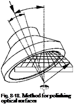
Polishing methods are divided into area polishing and zonal polishing (Fig. 8-18). When polishing with flat tools, the desired shape is transferred into the tool basin and transferred to the workpiece during subsequent processing. The tool is larger than the component being polished. This technology is used especially for finishing spheres and planar surfaces. For polishing aspherical geometries and freeform surfaces — and also for a targeted correction of spheres — zonal methods are necessary. According to this principle, the tool is significantly smaller than the workpiece. The advantage of polishing with flat tools is that removal over a large area is possible, which facilitates higher removal rates. Also, contrary to zonal polishing, the risk of the formation of structures on the surface is avoided.
When producing planar surfaces, polishing machines with lapping kinematics are also used. The production of planar surfaces is particularly important for finishing substrates like blank mask, wafers, etc.
 |
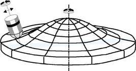 |
Area polishing Zonal polishing
Area Polishing Methods
Area polishing methods are of great economic importance. In industry, not only swivelling and horizontal lever machines, but also CNC-controlled machines are used for area polishing purposes.
Fig. 8-19 illustrates the kinematics of a horizontal lever machine. The oscillating swivelling motion of the lever, at whose anterior end a spherical joint pin is fastened, is initialised by the rotary motion of an eccentric wheel. A sliding-crank transfers the eccentric motion to the lever. The lever amplitude is manipulated by changing the distance of the sliding crank contact point from the rotation axis of the lever. The arrangement of the tool relative to the workpiece depends on the
size proportions of both elements. Usually, given a diameter ratio of the glass/supporting body with the glass parts to be polished to the abrasive carrier ranging from 1:1 to 1:1.5, the workpiece is placed above the tool. Given ratios between 1:1 and 1:0.9, the placement is reversed [KALL80]. In the process, the tool/workpiece that is below is driven constantly while the upper process partner remains freely movable, mounted on the spherical joint pin. Through the superposition of the lever amplitude and the forced rotary motion of the lower partner, however, the upper glass body and the above-placed abrasive carrier, respectively, is also set into an unforced rotary motion [KALL80].
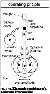 |
The friction force between the workpiece and the abrasive carrier is generated by the weight of the supported process partner. An influence on the active forces thus presupposes an appropriate dimensioning of the workpiece body/the abrasive support basin. Also, a slidable weight is positioned at the rear end of the swivelling lever. In accordance with the law of the lever, by selecting different distances of this weight from the support point of the lever, the normal force at the polishing level can be varied.
Changing the lever amplitude has a decisive influence on the polishing result. Thus, when using polishing pitch, there is a demonstrable influence of the flow speed of the surface layer of the material on the achievable shape accuracy. The
flow speed, which in turn determines the friction forces and thus the removal, is a function of the position on the polishing basin.
The flow speed can also be altered by changing the lever amplitude or modifying the surface shape of the polishing pitch.
 |
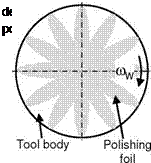 |
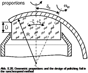
In the synchrospeed method, tool and workpiece are engaged at a certain angle in a defined manner. They rotate with almost the same angular velocity in the same direction. The workpiece and tool axes intersect in the radius mid-point of the workpiece (Fig. 8-20). In accordance with the Preston hypothesis (equation 8.1), the same removal values appear at every point of the workpiece given the same specific contact pressure p and a constant process magnitude K [KLOC98]. For the mechanical and technical implementation of this idea, two spindles driven separately from each other are needed to position tool and workpiece relative to each other. A further adjusting axis (B-axis) is necessary to set the angle d0 between the tool and the workpiece and to execute the oscillatory motion. An oscillatory movement is necessary when the proportions of speed become unfavourable because of an excessively large lens aperture angle x and a consistent relative speed can no longer be assumed about the circumference.
Another essential aspect of the synchrospeed principle is the design of the polishing foil. In addition to the removal at the workpiece, wear can also be observed on the polishing foil. In order to achieve an exact, durable workpiece shape, the tool must retain the original form it received through the initial dressing process. For this, a wear of the polishing foil must occur in the direction of the tool axis. During machining, however, not all areas of the foil are engaged for the same amount of time. For this reason, a small amount of wear occurs in these zones of the polishing foil. In order to achieve a consistent level of abrasion, the zones which are engaged for shorter periods are reduced so that the sum of all radial
contact lengths in a ring segment yields to the overall design of the polishing foil. Through this arrangement of lamellar geometries (Fig. 8-20) and the resultant pressure conditions varying according to zone, an equal material removal and tool wear can be approximated [KLOC98, HAMB01].
The setting parameters for this machine type are pressure, rotational speed, machining time, the rotational speed ratio and excess length (Fig. 8-20). Furthermore, an oscillation can be set for the machining of lenses with large aperture angles, making oscillation duration and oscillation stroke two further parameters one can control [HAMB01].