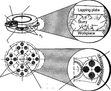
Different from lapping with one disc is the double-sided, simultaneous machining of two opposing planar surfaces (Fig. 8-6). In this method, the workpieces are inserted in geared carriers (rotating discs). These are held by pin rings or gear rings. Then they are driven, they rotate about both their own axis and the central axis. The workpieces describe an epicycloid or hypocycloid orbit between the machining discs (Fig. 8-7).
The lapping slurry is added through the upper machining disc. Through the change in direction of all driven axes, movement in the same direction or opposing directions is generated either inside or outside on the machining disc.
Usually, the workpieces are only inserted in the outer part of the carriers in order to alleviate pressure on the centre ring of the machining discs resulting from excessive surface area and a short run distance. The working pressure is raised by the pressure system of the upper disc and can be varied as necessary.
Another advantage of the double-disc system is the dimensional control through a central scanner or external scanning, which affords dimensional accuracies of ± 2 |im.
In the method known as clean lapping, diamond or cBN machining discs are mainly used. Constantly filtered oil or water is used as rinsing and cooling fluid, respectively.
Both soft and very hard workpiece materials, e. g. plastic or sapphire, can be machined using this method. Depending on the machine size, level workpieces of 0.1 to 100 mm thickness or round workpieces of 5 to 500 mm diameter can be lapped.
Lower lapping plate
![]()
![]()
![]()
![]()
![]()
 /
/
Workpieces
![]()
 |
inner pin rim (driven)
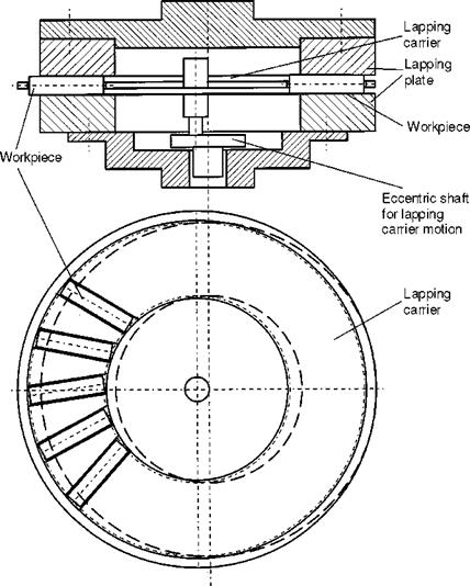
A particular feature of the double-disc principle is peripheral cylindrical lapping. In this method, the workpieces are held radially in a large carrier at a slight angle to the disc axis (Fig. 8-8). This method removes material due to the angled
position of the workpieces (lateral slipping during rotation). Accuracies of up to 0.2 pm of roundness and straightness, respectively, can be achieved. The removal rate is 10 to 20 pm in 10 minutes.
|
Fig. 8-8. Workpiece and lapping carrier configuration in cylindrical lapping [STAE95] |