
In lapping, the work surface rubs against the workpiece surface to be processed. Machining is achieved by means of the insertion of a lapping slurry (lapping grains and fluid) into the working gap between the machining disc (the tool) and the workpiece. In the process, loose grains (cutting edges) are added either continually or intermittently. The existent dependencies and interdependencies, respectively, are complex [WAGE94]. Fig. 8-1 shows the machining process for lapping.
|
|
|
|
|
|
|
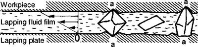
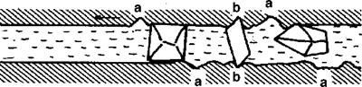
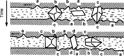
Fig. 8-2. Movement and effect of the lapping grains in the lapping film [MART72] |
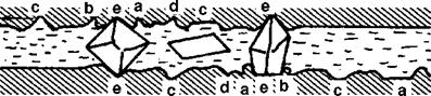
Material removal occurs as a result of the effect of the grain rolling in the contact zone between workpiece and machining disc surface or grains temporarily fixed in the disc surface. The edges of the lapping grains insert themselves into the
workpiece material (Fig. 8-2). The depth of insertion depends on the surface strain and the material, usually between 5 to 10 % of the average grain diameter. Through the vortex developing in the fluid film (pressure and suction forces), the lapping grains straighten themselves out and become engaged. Their edges, which are moving along cycloidal paths, engage the surface. Through the repeated penetration of the grains into the workpiece surface, ductile materials are reshaped until fatigue, and then successively removed. In the case of hard and brittle materials, however, microcracks are induced on the surface of the workpiece, the interconnection of which leads to the breakaway of particles [SIMP88].
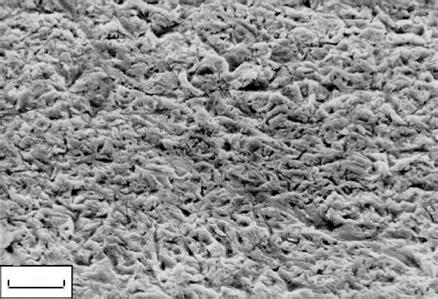 The surface receives its appearance through the overlapping of the crater-like traces of the total indentations from the engaged grain edges. Groove-shaped processing traces suggestive of material removal caused by a cutting process are not visibly recognisable (Fig. 8-3). Material-dependent hardening is associated with an embrittlement of the material and is indicated by an increased surface hardness.
у •»
5 ціп
I I. * r —
Fig. 8-3. Lapped workpiece surface
It is possible to subdivide lapping methods according to the active surface of the lapping tool. The term peripheral lapping applies when the tool axis and the workpiece surface are parallel to each other, and side lapping when the tool axis and the workpiece surface are perpendicular to each other. Fig. 8-4 shows some examples of different lapping methods.
In the following, some lapping methods will be introduced.

![]()
![]()
 |
|
e) Ultrasonic lapping 7. Oscillation trunk