In honing, cutting speed has a direct influence on the material removal rate. If the contact pressure is given, which determines the number and cross-section of the chips, the cutting speed indicates the average chip length achieved per time unit and thus the material removal rate (Fig. 7-12).
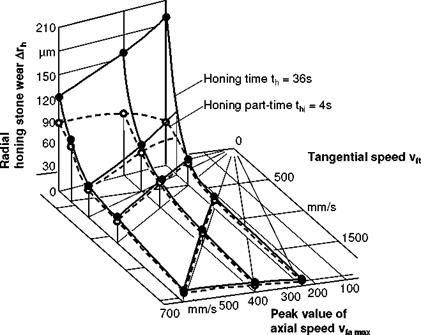
The generation of cutting speed vc from its components vfa and vft is decisive for the plot of the curves. According to the cross hatch angle a, the workpiece surface is subject to varying grain engagement. The corresponding changes to the material removal rate result from processes on the tool. The strain and wear of the tool increase with the cross hatch angle a. The reason for the increasing wear can be reasoned by the varying mechanical stresses on the individual grain. The applied forces change according to position, extent and direction according to the cross hatch angle a. The greater the differences are in force application direction, the more probable it becomes that the anisotropic holding forces between grain and bond will be exceeded. Given a large cross hatch angle a, the grains tend to break away, releasing the sharp grains underneath.
|
|
 |
Fig. 7-13. Honing stone wear as a function of the speed ratio
 |
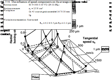
Fig. 7-14 shows surface roughness as a function of cutting speed. According to this graph, cutting speed has a positive influence on surface quality. Proceeding
from a considerably higher degree of roughness created in pre-machining, a large amount of initial roughness is removed at higher material removal rates.
In order to compare the best possible roughness values, conditions must be selected in which the initial condition of the tool has no influence, i. e. after a sufficiently long machining time, with a low material removal rate. As shown in Fig. 7-14, the influence of cutting speed on roughness is considerably reduced given a high material removal.
The correction of cylindricity and roundness errors also depends on the composition of the cutting speed.
The superposition of the optimal speed components (circumferential and axial speed) resulted in a cross hatch angle a = 45°. The connection between the cross hatch angle a and shape errors can be explained primarily by the fact that the material removal rate reaches its maximum value at a = 45° in many other processes, as well. Although these values are only optimal in individual cases and thus do not allow for generalisation, it is nevertheless clear that a high material removal rate is required for the correction of shape errors.

