
The principles of the honing process will be explained using the example of short — stroke honing. The movement between tool and workpiece can be divided into three orthogonal speed components (Fig. 7-1):
• two components parallel to the workpiece surface (axial feed rate vfa, tangential feed rate vft)
• one component perpendicular to the workpiece surface (feed rate vfn)
The speed components superpose to form the cutting speed:
Vc =VV fa + V ft + V fn (7Л)
Since vfn is very small in comparison to vfa and vft, because of the lower material removal, we can calculate vc to:
Vc = Vvfa + vft • (7’2)
Speed and direction depend on the kinematics of the tool drive. The tangential feed rate vft is generally constant. The axial feed rate vfa is an oscillating movement describing a sine-wave. Proceeding from the path function (Fig. 7-2), we obtain the formula
![]() y = — sin{cot) 2
y = — sin{cot) 2
with y being the path of oscillation and l0 being the oscillation amplitude. Following this, we obtain
![]()
 |
vfa = y = l-f °)cos i0)t).
Alternately, introducing the stroke frequency f = yields
![]()
 |
Vfa = hnf cos{rn).
According to equations 7.2 and 7.5 and taking account of the superposed axial workpiece speed vwa, the speed vc is calculated as
V = ^v^2~+(l0nfcos((UtyrVWaf (7.6)
with the maximum value
V =Vvft + ((nf + Vwa f. (7.7)
The minimum value is
V = vft. (7.8)
The cross hatch angle a is calculated as
![]()
|
|
|
|
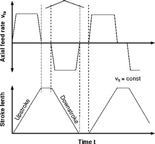
In the case of longitudinal stroke honing, the relative motion between workpiece and tool generally corresponds to those in shortstroke honing. Whereas in shortstroke honing of cylindrical workpieces the workpiece usually effects the rotational movement, in longitudinal stroke honing, the tool generates both the axial movement and the rotation. Fig. 7-3 shows the kinematics involved and the resultant surface pattern.
In contrary to shortstroke honing, the axial movement does not describe a sine — wave oscillation. The axial speed remains constant over the entire stroke length except at the turning points.
The speed vc = Vfa + vft is thus calculated as
In accordance with equation 7.9, a constant cross hatch angle a is obtained in case of constant axial and tangential speed, which only yields smaller values at the ends of the workpiece, i. e. in the turning position of the tool. In addition to the oscillatory movement shown in Fig. 7-4 without stroke delay, a stroke delay can also be included for reasons of shape accuracy in one or both turning positions (Fig. 75).
The resultant reduction of the cross hatch angle a in the vicinity of the turning points is corrected as a result of their being a number of strokes without stroke delays at the end of the machine run.
The tool is feed controlled in direction of vfa and vft. In force or feed direction of vfn, i. e. perpendicular to the workpiece surface, movement is force or feed controlled. The depth of cut is generated by hydraulic or mechanical positioning mechanisms (Fig. 7-6).
The contact pressure of the honing stone on the workpiece surface is calculated in line with Fig. 7-6 as
|
|
|
|||
![]()
|
honing pressure
between honing stone
and workpiece
|
