
As precision components in internal combustion engines, valves control the necessary gas flow by blocking cross-sections of flow. While inlet valves are subject mainly to mechanical stresses, outlet valves are also exposed to thermal stress and chemical corrosion. Valves are therefore manufactured from various materials depending on their function.
In the case of many high-stress outlet valves, the mechanical and physical properties of two or three different materials are combined. These so-called bimetallic valves fulfil the demands on heat and corrosion resistance of the valve head with sufficient shaft toughness (Fig. 6-144).

In the example under discussion, austenitic steel X 50 CrMnNiNbN 21 9 (1.4882) in a precipitation hardened condition (> 30 HRC) serves as the valve head material. The shaft consists of heat-treated steel X 45 CrSi 9 3 (1.4718, hardness 57 +/- 2 HRC) that is connected to the valve head with a friction weld. In order to reduce wear, the thermally and corrosively stressed seat can be armoured with special alloys, e. g. stellite, a cobalt-chrome-nickel alloy. In addition, the valve shaft is coated with chrome and the valve shaft end is hardened.
Form, dimension and surface quality of the valve are produced by means of different metal cutting processes. As a manufacturing method, grinding lends itself to machining high-alloyed and thus hard-to-cut materials.
The valve shaft is processed before and after chroming with centreless infeed grinding (Fig. 6-145). This method is a process in large batch production and allows a high level of accuracy in concentricity even for slender components like the valve shaft. The valve shaft guides and centres the valve and serves to get rid of the heat caused by combustion from the valve head through the shaft to the cylinder head. Interaction between the guide hole and the valve shaft should be minimal in order to guarantee a low amount of valve guide wear. The centreless pre-grinding process under consideration must realise a roundness error fk = 8 |im and an average surface roughness of Rz < 10 |im.
The grinding wheel used is a sol-gel-corundum grinding wheel of granulation 100 in a ceramic bond. Its external diameter is 500 mm and its width is 100 mm. The control wheel is made of rubber-bonded corundum and has an external diameter of 300 mm. The workrest blade has a width of 3.5 mm. Grinding oil is used as the cooling lubricant.
|
|
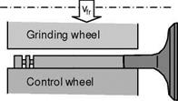
Fig. 6-145. Centreless infeed grinding of the valve shaft
The grinding wheel is dressed with a dressing plate, the control wheel with a single-grain dresser in accordance with the dressing parameters given in table 610.
|
Table 6-10. Dressing parameters
|
The grinding process is undertaken with the parameters given in table 6-11.
|
Table 6-11. Process parameters
|
In the grinding process, two different materials are simultaneously engaged, which puts different stresses on the grinding wheel. The long-chipping austenitic head material, which is prone to clogging, leads to higher grinding wheel wear than does the heat-treated and partially hardened shaft material.
Furthermore, the different cutting properties of the ground materials lead to torsion of the valve head against the shaft. The materials can also exhibit different reactions to the heat introduced during grinding. When the heat-treated/hardened shaft material warms up, re-hardening or annealing effects can result. The austenitic hard material on the other hand undergoes no structural changes during the relatively short action time of the grinding heat.