
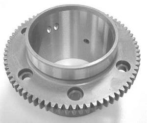
The manufacture of a gear component should entail grinding of the interior surface (Fig. 6-141).
This hole is a functional are guaranteeing the correct sitting of the gear on the shaft. The hole is specified in diameter, surface roughness, roundness and concentricity by the associated parameters (Fig. 6-142).
The component consists of the material 16MnCr5 and was case-hardened prior to final machining. This produced a surface hardness of 760 (+/- 40) HV with a hardening depth of 0.8 mm.
|
Fig. 6-141. Gear component with a ground interior hole |
![]()
 |
The challenge in this machining task is in obtaining the target surface quality. This requires a fine-grained and finely dressed grinding wheel, which on the other hand has only a small amount of pores. This is disadvantageous in interior grinding processes due to the contact length and the poor swarf removal. Because of this conflict, an open-pored, coarse-grained disc was selected here. Moreover, the process stages were subdivided up to the finest grinding process with a very low material removal rate and a long spark-out in order to obtain the target surface quality.
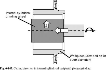
The hard machining process takes place with the internal cylindrical peripheral plunge grinding method. For this it is necessary that the grinding wheel is wider than the area to be ground, since the process occurs in one infeed (Fig. 6-143). After pivoting the grinding wheel into the hole opening (1.), cutting takes place radially and outwardly (2.). The workpiece is clamped externally in a three-jaw chuck.
|
|
Processing occurs with an internal cylindrical grinding wheel (diameter 50 mm, width 70 mm) of specification A 60 K 10 (corundum in a ceramic bond). An emulsion (3 %) is used as the cooling lubricant. A dressing plate, a stationary dressing tool, is used for tool preparation in accordance with table 6-8.
Grinding is subdivided in total into five process stages. In each process stage, the radial feed and thus the material removal rate is reduced until the final dimensions are obtained. This has the objective on the one hand of reaching the target surface quality and on the other of minimising errors in form caused by grinding forces during the process. The parameters are found in table 6-9.
|
Table 6-8. Dressing parameters for the peripheral surface of the applied corundum internal cylindrical grinding wheel
|
|
Table 6-9. Parameters for the particular process stages:
5 seconds spark-out |
For this machining task, internal cylindrical peripheral longitudinal grinding can be used here as an alternative method. For reasons of productivity, plunge grinding was used in this case. Despite the subdivision into five process stages, the process can be executed relatively quickly. In the case of longitudinal grinding, it would be necessary to carry out several axial overruns in order to preserve the required surface quality and formal and positional tolerances. These are slower in total than infeed with a grinding wheel that is wider than the workpiece. A men — tionable disadvantage of insertion in this case is that the grinding forces are higher because of the larger effective grinding wheel width bs eff.