
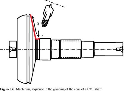
When manufacturing a CVT shaft (continuous variable transmission), an conical area is machined. This component is used in automobile transmission. There is a belt on the cone that transfers force in a frictionally engaging manner. The transmission can be altered continuously by the position of the belt on the cone. Accordingly, the cone is a functional surface on which a final machining should occur by means of high-performance external form grinding. The material used is 51CrV4, which attains a hardness of 58 — 64 HRC by means of induction hardening.
For this, the radius transition of the cone to the bordering cylinder is first provided via insertion with the grinding wheel. Then the processing of the cone surface takes place. Directly following the insertion process, the grinding wheel is guided upwards along the cone contour under NC control (Fig. 6-138).
|
|
The grinding tool used is a segmented grinding wheel with a steel body and with cBN as the grain material in a ceramic bond of specification B126 VSS 3441 J1SN V360 E. The grinding wheel has a diameter of 500 mm and was already pre
profiled during manufacture in accordance with the angled position of the grinding spindle.
Machining occurs on an external grinding machine designed for high-speed cutting and attaining grinding wheel peripheral speeds of vs = 210 m/s. A diamond form roller is used as a dressing tool, which forms the peripheral contour of the grinding wheel via NC control. A grinding oil based on a polyalphaolefin is used as a cooling lubricant and applied with a free jet nozzle.
 |
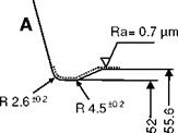 |
The components requirements are defined in Fig. 6-139 using various parameters.
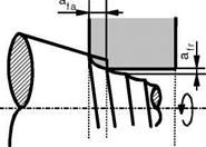
The challenges in the machining task presented here lie in grinding the conical surface while adhering the prescribed tolerances, especially surface roughness Ra. In conical grinding, machining occurs only with the radial edge by means of the profiled grinding wheel with the radius contour and the cylindrical peripheral surface (Fig. 6-140). A spark-out zone, such as one finds in grinding cylindrical workpiece contours, and a correspondingly high overlap ratio are not found here.
In this case, theoretically a spiral-formed groove similar to a thread is ground into the workpiece. In principle, it is possible to select such a small infeed that the form errors remain within the range of acceptable surface roughness [Kamm91].
|
Fig. 6-140. Engagement condition of the grinding wheel when grinding a cone [HEGE98] |
For machining, the grinding wheel was profiled with a diamond form roller in accordance with table 6-6.
|
Table 6-6. Dressing parameters for the shoulder and peripheral areas of the applied cBN grinding wheel
|
The grinding process of the recess and of the cone took place in accordance with the process parameters in table 6-7.
|
Table 6-7. Process parameters for recess and cone
|
The speed ratio of q = -50 was determined here for the beginning of the cone area and set with a workpiece speed that is constant for the process. Accordingly, the speed ratio deviates from this value at the end of the cone contour.