
6.6.1 External Cylindrical Peripheral Plunge Grinding
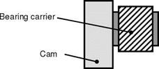
In the end machining of camshafts for engines, not only the control cam, which activates the valve tappets, but also the bearing carrier must be machined (Fig. 6136). In order to guarantee smooth operation, the bearing carriers are tolerated with respect to surface roughness, roundness and concentricity. The material used is 100Cr6V, hardened to 58 HRC and tempered.
The hard machining process takes place with the external cylindrical peripheral plunge grinding method. A grinding wheel with conventional grains is used as the grinding tool. This is a solid body disc of white corundum in a ceramic bond of specification A 120 L 5. The grinding wheel has a diameter of 400 mm and a width of 25 mm and is marginally wider than the bearing carrier to be machined. Machining occurs on an external grinding machine that clamps the workpiece between centres and facilitates support by means of a steady rest in order to avoid deflexion. A diamond form roller is used as the dressing tool. The cooling lubricant used is an emulsion (3 % concentration).
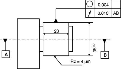
The component/form element requirements can be derived the sketch in Fig. 6137.
|
|

|
Fig. 6-136. Schematic representation of a camshaft |
|
Fig. 6-137. Requirements on the bearing carrier of the camshaft |
The width of the grinding wheel is selected such that machining can take place in one feed. The goal is a machining of the bearing carrier that is as productive as possible. For this reason, the plunge grinding process is subdivided into roughing, finishing, fine finishing and sparking-out. Most of the stock allowance is removed with a high specific material removal rate in as short a time as possible. In the subsequent finishing, fine finishing and sparking-out phases, the form errors introduced by workpiece deformations during the roughing process are evened out again and the required surface quality obtained.
During the tool preparation process, the grinding wheel must be dressed such that a topography is obtained that is both conducive to a high material removal rate during roughing and can also achieve the required qualities with the selected process stages. The dressing parameters as chosen in accordance with table 6-4.
|
Table 6-4. Dressing parameters for the peripheral surface of the applied corundum grinding wheel:
|
For the subsequent grinding process, the following process parameters were selected shown in table 6-5:
|
Table 6-5. Process stages during the grinding of a bearing carrier of a camshaft
3 seconds spark-out |
By means of support with a steady rest, a specific material removal rate can be reached in the roughing phase that allows for a short machining duration. A fraction of the process forces thereby created is channelled off into the machine bed by the steady rest. A deflexion of the workpiece and thus the development of form and positional tolerance deviations and can however not be completely eliminated. By means of multi-stage processes however, process forces are reduced to such an extent towards the end of the process that the component can be returned to its original position and the accrued errors eliminated.