
The high surface qualities obtainable in principle from grinding can be negatively influenced by oscillations in the machine. Relative displacements in the grinding contact zone, caused by externally or internally induced vibrations, arise on the workpiece surface as a function of the grinding process’s kinematics and lead to more ripples and roughnesses in the ground surface. Especially in precision machining, for creating higher surface qualities, even the smallest relative displacements in the grinding contact zone lead to clearly visible surface markings that are barely quantifiable with tactile surface measurement systems. Relative displacements during grinding must therefore be avoided or minimised as much as possible.
Basically, we differentiate between externally and self induced vibrations with respect to their origin or cause (Fig. 6-132) [WECK92, WECK95].
•  Unbalances
• Positional error,
defective machine components
• External forces (induced via machine bed)
• Discontinuous cut
Fig. 6-132. Distinguishing characteristics of externally and self induced vibrations in grinding operations
In the case of externally induced vibrations, a disturbance with the frequency and amplitude of the inducer is introduced into the process. This type of vibration is formed periodically as a disturbance on the component surface as a function of the cutting and feed motions. For example, grinding wheel concentricity errors and imbalances in the rotational speed ratio between the grinding wheel and the workpiece arise in external cylindrical peripheral grinding, determining roundness errors to a large extent. Especially in precision machining therefore, machine components like main spindle drives and workpiece drives are precision-balanced. Disturbing forces which can be introduced via the machine’s foundation should be avoided with a suitable vibration-isolating machine assembly [WECK92]. For example, a precision grinding machine should not be set up near press equipment or other machines that send vibrations through the floor.
Self induced vibrations appear without the external influence of disturbances, whereby often only one grinding machine component vibrates with its characteristic frequency. If we reduce the vibration problem to the case of the damped single mass oscillator, the amplitude of the oscillation will increase disproportionally, reaching its resonance frequency when the phase angle between the oscillation and the agitation arrive at about 90°. In the case of regenerative chattering coming from the workpiece for example, the workpiece can be agitated by the dynamic fraction of the cutting forces in its characteristic frequency. As a rule, when there is regenerative chattering with high amplitudes, as is the case with externally induced vibrations, the oscillation is acoustically perceptible, and oftentimes visible markings are formed on the workpiece surface. Especially in case of high oscillation amplitudes, these disturbances clearly influence the component’s quality, e. g. roughness and roundness errors. Grinding processes that take place in dynamically unstable conditions not only produce significantly worse quality workpieces, but also subject the grinding wheel to much more wear.
Measures aimed at avoiding regenerative chattering of the workpiece are often only possible after a dynamic investigation of the grinding machine [WECK92].
Initial indications of whether the oscillation problem in the grinding process is
of an external or internal nature can be obtained when the grinding width and thus the grinding process forces are reduced. If it is a case of an externally induced vibration, the characteristic oscillation frequency does not change, and so neither does the component quality. In the case of regenerative chattering of the workpiece on the other hand, the reduced grinding forces lead to a lower oscillation amplitude in the noise created by the cutting forces. So, beyond a maximum dynamic grinding force typical for the component, the grinding process will proceed stably. Markings on the workpiece and roundness errors are reduced. The consequence for the grinding process is that the specific material removal rate has to be considerably reduced, which often can lead to undesirably long machining durations. It is in this case much more advantageous to stabilise the grinding process by means of constructive measures relating to the machine, for example, by using backrests or by means of active or passive dampening measures [GOSE90, JANO87, STAP79, TELL86, TOEN88, WECK91].
Besides such constructive measures aimed at the grinding machine for reducing its proneness to chattering, the selection of process parameters has a decisive influence on the stability of the grinding process. For example, the same specific material removal rate Q’w can be realised with different combinations of depth of cut ae and workpiece speed vw.
In investigations on dynamic grinding process behaviour, the influence of process parameters on regenerative workpiece and grinding wheel chattering has been explored and limiting phase curve derived as stability criteria [ALLD94]. If one of the limiting phase curve intersects the phase angle of machine flexibility, a necessary condition for regenerative chattering has been fulfilled. It basically shows that an increase in the depth of cut ae is conducive to stability. Therefore, especially with grinding processes that tend toward dynamic instabilities, the workpiece speed should be reduced as much as possible. It must be taken into consideration in this case that, with a falling workpiece speed vw the danger of thermal damage to the external zone increases.
The prerequisite for carrying out a reproducible grinding process with constant workpiece quality is the reduction of externally induced vibrations to the greatest extent possible. Here, attention should be focused above all on grinding wheel concentricity errors and grinding tool imbalance. With the rotational speed ratio between the grinding wheel and the workpiece, these show on the ground surface as ripples. As a rule, the number of markings formed on the workpiece surface corresponds to the rotational speed ratio and is an indication for the causes mentioned above. Grinding wheel concentricity errors are to be eliminated during the use of dressable grinding wheels by means of a conditioning process. Non — dressable grinding wheel types, such as galvanic CBN grinding wheels, require a concentricity alignment of the grinding wheel with respect to the spindle rotation axis that is as exact as possible. The roundness error of the mounted grinding wheel should lie within the fabrication tolerances of the grinding wheel as much as possible. High-precision, galvanically bonded cBN and diamond grinding wheels generally possess an alignment cylinder running exactly along the hole and the coating, with which the grinding wheel is aligned to 0.001 mm. High-precision grinding wheel clamping devices or exchanging completely mounted spindle systems are also known. As a rule, aligning grinding wheels demands increased assembly time, which can be reduced to a minimum by using modern clamping systems in accordance with DIN 69063. The grinding wheel and clamping system are firmly connected with each other, and the abrasive coating possesses a minimal roundness error with reference to the contact surfaces of the clamping device.
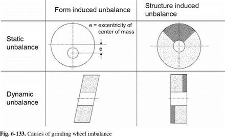
Besides minimising faults in grinding wheel roundness, a precise balancing of the grinding tool is required. In the case of grinding wheel imbalance, we distinguish between form-induced and structure-induced imbalance (Fig. 6-133). Form — induced imbalance arises from dimensional and form errors in the manufacture of the grinding wheel. Despite adherence to exact shape and dimension tolerances, it can be avoided to a large extent, but never fully.
Structure-induced imbalance is caused by local differenced in grinding wheel density.
|
|
After clamping, the grinding wheel is dressed on an exact concentricity. By means of lateral dressing of the wheel, imbalances resulting from non-parallel lateral surfaces can be eliminated. Dressing only removes form-induced imbalances. Structure-induced imbalances and residual form-induced imbalances on the other hand can only be compensated by means of a subsequent balancing of the grinding wheel. This is why this process is necessary before every grinding wheel implementation. As a rule, only static imbalance is removed in the case of grinding wheels. Only very wide grinding wheels, as are used for example in centreless grinding, require a dynamic balancing. Balancing is carried out in two levels [DURS77]. The concepts of balancing technology are defined in DIN ISO 1925.
Imbalance is defined as the product of the unsymmetrical mass mR and the distance r of this mass from the rotation axis. The distance of the centre of mass from the rotation axis is designated as the distance of the centre of mass or residual imbalance e. We thus obtain from the ratio of imbalance and the rotating mass M:
U
e = — (6.99)
m
The balancing quality Q can be determined as a function of the residual imbalance e and the angle speed ro of the grinding wheel as follows:
Q = e ю (6.100)
Common balancing qualities for dressing rollers are Q = 1 and for grinding wheels Q = 2.5.
During the grinding process, the grinding wheel wears out and can be clogged with chips. New imbalances are thus constantly cropping up during grinding, making a further balancing indispensable — especially in precision grinding operations.
Balancing stationary grinding wheels is of only minor importance in industrial praxis, since in order to accomplish this, the grinding wheel, including the grinding wheel flange, must be removed from the machine and mounted on a rolling stand. As a result of unequal mass distribution in the grinding wheel, it wobbles on the balancing scale until the centre of mass is below the rotation axis. Then two to three sliding blocks are shifted in a notch on the circumference of the flange until the grinding wheel comes to rest at any arbitrary position on the rolling stand. The method is now employed only for pre-balancing very large grinding wheels and when main drives are used that are not speed-controlled, making a pre-balancing of the discs impossible at low rotational speeds.
When balancing methods are utilised with rotating grinding wheels, the tool mounted on the grinding wheel flange is balanced on the main spindle of the machine. If balancing only occurs on one level, the systems balancing with the rotating wheel are also designated as static balancing systems.
Short balancing times are obtainable by using automatic balancing systems. Modern electronics and control engineering have made it possible to develop inexpensive devices for balancing grinding wheel during the machining cycles. These are, for example, hydro compensators and mechanical balancing systems that electromechanically shift balancing weights during operation of the main spindle.
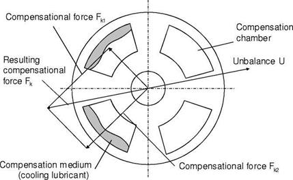
Hydro compensators function without mechanical components. They use the cooling lubricant present in the grinding machine, spraying it in a targeted fashion into the balancing chambers. Its workings can be described as follows (Fig. 6134).
The temporal progression of a head stock oscillation caused by grinding wheel unbalance U is captured by the oscillation sensor. The position of the centre of mass of the unbalance can be determined with the help of an inductive sensor. The unbalance, known from its position and amount, must be compensated with a compensatory mass. To achieve this, the required position of the compensational weight K is determined electronically according to the relative position of the unbalance and is analysed into the components k1 and k2. This point in the direction of the surface centres of gravity of the fluid chambers.
|
Fig. 6-134. The basic principle of hydro compensators (Hofmann Bros.) |
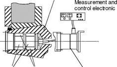
By means of the magnetic valves driven by measurement and control electronics, the compensation medium, usually a cooling lubricant used in grinding, arrives at the nozzle block mounted at the protective hood. By means of fine nozzles, and a port system in the fluid container, the compensation medium is sprayed into the compensation chambers until the unbalance is below a preset lower threshold. If the state of balance changes as a result of grinding wheel wear, balancing can take place automatically in a very short amount of time, e. g. during the workpiece loading. If frequent balancing is required, at least one of the compensation chambers will be filled with the maximum amount of fluid volume, making further balancing impossible. If this state is reached, the main spindle must be switched off so that the balancing chambers can empty themselves. A further disadvantage of this system, especially in the case of retrofitted main spindles with a balancing container mounted on the front face, is that a dismantlement of the balancing container is required during grinding wheel change and, if the grinding wheel width has changed, the spraying nozzle unit must be reset.
Further developments in the field of mechanical balancing systems are circumventing this problem. In these systems, the position of the balancing weights set electronically after the first balancing remains, making possible a deceleration and acceleration of the main spindle without intermediate balancing. Fig. 6-135 shows a mechanical spindle-integrated balancing system. This balancing system is installed into a cylindrical hole in the main spindle and consists of two balancing weights that can be rotated relative to each other electromotively. The adjusting motors and transmission gearing are arranged centrically on the rotation axis of the spindle in order to keep centrifugal stress as low as possible. The adjusting motors are directed by an electric controller built into the balancing head that is supplied with energy and control signals via a non-contact transmission line. The contact-free transmission line, depending on the operator, can be placed on the spindle nose or on the actuator side of the main spindle. Furthermore, the existing transmission line can simultaneously be used to transmit measurement signals, e. g. mechanical vibrations. This opens up the possibility of capturing and transmitting the process-relevant measurements of a rotating grinding wheel with a small amount of dampening joints during the grinding operation. Free accessibility to the grinding tool is advantageous to the operator, potentially leading to a considerable reduction in machine set-up time. Future developments of these systems will make available rotational speeds of n > 10000 R/min and are indispensable for grinding with high cutting speeds [WECK92a].
|
Main spindle
actuator Com^n^tton Contact distance and electronics masses transmission line Resulting Fig. 6-135. Construction and workings of an electromechanical spindle-integrated balancing system |
 |
The workings of an electromechanical balancing system are comparable to those of a hydro compensator. Here too, there is a detection of oscillation amplitude by means of an oscillation sensor and the spindle rotation frequency. These signals are processed in an electronic controller. Thus during a measurement interval of ca. 2 seconds duration, the maximum of the unbalance oscillation is determined and corresponding control signals are transmitted to the electronics in the rotating balance head in order to position the compensation weights. If the unbal-
ance oscillation is reduced during one measurement interval, the compensation weights are shifted continually in the same direction until the oscillation speed increases slightly after running through a minimum. If the oscillation amplitude is above a presettable boundary value, a new adjustment cycle of the balancing weights occurs, whereby the adjustment direction of one or both weights is altered. The minimising process is ended when it fall below the preset threshold value and the unbalance U is compensated by the centrifugal forces Cf1 und Cf2. This is shown in Fig. 6-135. The balanced state once created remains stable so that after the main spindle is turned off and in the subsequent run-up to the operational speed a new balancing is no longer required. It is only necessary to re-balance if there is an altered distribution of weight in the grinding wheel as a result of grinding wheel wear or from dressing.
Fluctuating temperatures and various increases in heat in the grinding wheel lead to thermal deformations and machine component displacements and are as a rule detectable as dimensional faults on ground parts. We differentiate between interior heat sources and environmental thermal influences. Examples of interior heat sources are drive motors, bearings, hydraulic systems and process heat arising from machining. In the case of modern grinding machine we assume as a rule that the machine manufacturer has considered the influence of machine-specific heat sources on the displacement of components. Especially very fine grinding operations require a high level of thermal stability, which is often only obtainable by means of a suitable thermostatting of the equipment, e. g. hydraulic oils and cooling lubricants.
Environmental thermal influences on the other hand can be influenced to a large extent by the operator. The position of the grinding machine is of decisive influence on the precision obtainable. For example, either direct heat irradiation from the sun, radiators and systems with thermal operating principles or heat reduction from indoor gates, windows and foundations can be responsible for dimensional faults. Precision grinding machines are thus often set up in climate — controlled spaces.