
High material removal rates and the highest surface quality are mutually exclusive. For this reason, shortening the machining time by increasing the material removal rate is faced with severe limitations when the material removal rate is constant during the process. In this case one speaks of a single-staged process.
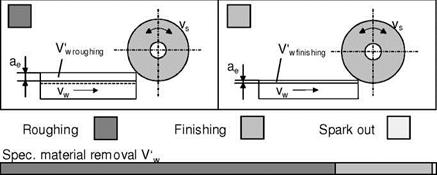
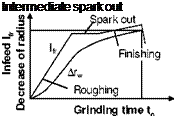
In roughing (Fig. 6-124), the volume removed from the workpiece per time unit is large. This leads to shorter production times and low machine and labour costs per workpiece. For the subsequent finishing phase, a workpiece material volume sufficient to achieve the required surface quality must be available. In this case, the material removal rate is very low, so the cutting duration in finishing can be longer than the roughing duration despite the minimal material removal.
|
Grinding time tc Fig. 6-124. Material removal and grinding duration in multistage processes |
The grinding wheel topography changes during roughing because of the high amount of grinding wheel wear to such an extant that it is no longer suitable for a subsequent finishing phase, as very long finishing durations are required to produce the target surface quality. It is thus necessary to optimise the multistage process. Method-related differences must be considered when doing so [BOET79].
The temporal progression of a two-step process for external cylindrical peripheral plunge grinding is represented schematically in Fig. 6-125. The abrupt reduction of the feed velocity when switching from roughing to finishing influences delayed the process parameters and the output. This is attributable to the fact that the
feed velocity actually present at the active site does not correspond to the one that was set, since the deformed total system relaxes from the abatement of the cutting forces.
processes
Only after the relaxation period (unsteady phase) are there process conditions, the effects of which can be derived from a nominal value of the parameters, as in single-stage processes. In order to evaluate a multi-stage process, one must know what kind of effect a parameter change has on the process and output in the roughing and finishing phases. These are, in particular, the material removal rate, material removal and the cutting and workpiece speeds.
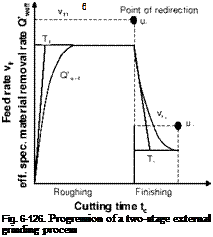
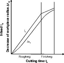
Fig. 6-126 shows the basic progression of a two-stage external grinding operation. Due to system deformation, the effective specific material removal rate Q’w eff as well as the reduction in radius of the workpiece Arw is delayed.
The delay complies to a large extent with an exponential function, the time constant T of which is a function of system rigidity and the cutting force. Beyond this, the course of the process also has an influence on the time constant T1. It could thus be ascertained that the time constant grows larger with increasingly blunt grinding wheels. The transition from roughing to finishing is also associated with a time delay. The time constant with which this occurs is, due to differing technological requirements, not identical to T1. It can however be approximated as equal to T1. The temporal behaviour shown for the material removal rate has dif-
 |
 |
ferent effects on the cutting forces, wear, surface quality and shape errors. Fig. 6127 shows the course of cutting force and surface quality as a function of the spark-out time ta [BOET79].
The spark-out process is a special finishing process in which the feed rate is vfr2 = 0. Here, system deformation is reduced completely, while at vfr2 + 0 a certain amount of deformation resulting from force during finishing remains.
During the spark-out phase therefore, the descent of the material removal rate is at its most rapid. In the upper portion of the illustration, we see the path of the normal force as a function of the spark-out time for various starting conditions, i. e. for different roughing processes. With initially smaller cutting forces, the time constant is larger, so the graph is flatter. In the lower part of the figure are plotted the relations of the average surface roughness Ra, corresponding to the courses of
force, to the spark-out time courses. It is conspicuous that the time constant for roughness improvement is larger that that of cutting force reduction and that the final state has different values. The reason for this is that the entire circumference of the workpiece must be ground before the roughness corresponding to the grinding conditions is realised. The final roughness is influenced by the condition of the grinding wheel’s topography, which depends in turn on the roughing process. After roughing, the effective surface roughness of the grinding wheel and thus the workpiece’s roughness as well is larger than that resulting from a small material removal rate [SALJ75, VERK78].
The larger effective surface roughness of the grinding wheel affects the process duration by decreasing the kinematic cutting edge number such that with smaller cutting edge numbers, the improvement of roughness also progresses more slowly.
Fig. 6-128 illustrates the influence of the feed velocity and the specific material removal on the transition behaviour using the example of surface roughness. A rise in the material removal rate as well as the increase in material removal during roughing leads to a displacement of the falling curve to higher values with a small alteration of the time constant preset by the system.
|
Input parameters Transient behaviour Roughing Finishing
Fig. 6-128. Falling roughness during finishing as a function of the feed rate and material removal |
With constant roughing conditions, the falling curve always begins at the same starting point. If the finishing material removal rate is increased with constant material removal, the duration of the finishing stage may indeed be shortened, but surface roughness cannot be improved significantly.
Raising material removal during finishing can no longer improve the surface quality after reaching the stationary phase. If other criteria, e. g. external zone influence after roughing, do not require the removal of a certain material volume, the grinding process can be ended when the stationary phase is reached. In cases of measurement-controlled grinding processes, the shifting point from roughing to finishing must therefore be set such that the final size is only obtained when the transitional phase is completed. Material removal and the rate thereof in finishing should be adjusted such that the finishing time tc lies in the range:
3T < tc < 4T. (6.98)
If surface layer influence is very large after roughing, a further finishing phase — and thus a three-stage process — can be advantageous [BIER76, BOET79].
In an initial finishing phase, the thermally influenced external zone is ground. The rest is then removed in the last stage with the lower feed velocity required to produce the surface quality. In praxis, the feed rate is generally two to three times higher in the first finishing stage than in the final phase.
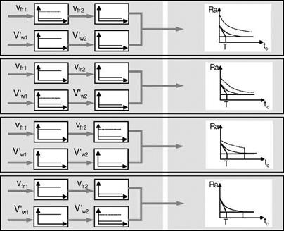
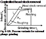
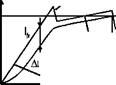
Besides these customary two or thee-stage processes, new, optimised process conduction and control variants are being increasingly used that are more effective against the disadvantages of unsteady process phases [VARL87]. Fig. 6-129 reproduces the temporal courses of the feed path lfr and radius reduction Arw for well-known control strategies.
The first process variant with the intermediate spark-out phase has the task of accelerating the easing system tension by turning of a radial feed rate after roughing. If the normal force or the elastic system deformation in the spark-out phase has reached the finishing level, the process switches to a final finishing feed rate. This finishing stage primarily has the function of reaching the preset nominal size of the workpiece. A significant improvement of workpiece quality, i. e. roughness and circular form precision, does not occur here, since these values have already been reduced to a minimal level by the intermediate spark-out.
The second variant is characterised by a rapid retraction of the head stock after the roughing phase. This reverse motion of the grinding wheel has the effect of removing the system deflexion built up during roughing in a very brief period of time. Especially in the case of flexible shafts, grinding time can be reduced considerably with this method, since the reduction of system stress, lasting very long with conventional processes, is cut down to a minimum. The best results with respect to workpiece roundness improvement are obtained by means of head stock removal when the system relaxation is completed within exactly one workpiece rotation. Finishing introduced after tension reduction has the task of improving workpiece roughness and lowering it to the required level.
Demanded. end radius
![]()
![]()

![]()
 Finishing r
э| wsoll
|
Controlled infeed
Grinding time tc |
If in head stock removal a mathematically determined, variable retraction speed is employed instead of a constant one, it is then possible simultaneously to eliminate roughing infeed spirals during relaxation. Thus, in the case of this type of process control, roundness deviation is already minimised at the beginning of finishing. The progressively increasing removal speeds necessary for this is to be taken from the third process control variant.
If we consider the first three, the following effects on the course of the process are clear:
• By minimizing the duration of relaxation, the grinding time is shortened.
• By means of controlled system relaxation to a residual value of grinding force or system deformation, a reproducible grinding process independent of disturbances is obtainable. This leads in improved uniformity in the quality of the finished part.
The goal of the fourth process variant is also more uniform process output, but also, as opposed to the previous processes, an artificially lengthened finishing phase. The slow, continual reduction of the radial feed rate brings about a large amount of material removal in the long finishing phase. For this reason, this process is utilised for grinding tasks for which a thermally influenced surface layer, unavoidable in roughing, must be securely and quickly removed. The mathematical determination of the altered speed profile during finishing is based on the following condition:
At every moment in the finishing phase, the momentarily produced depth of the thermally influenced zone should correspond to the material allowance still present on the workpiece.
If we observe this condition, the process results, with a correspondingly reduced radial feed rate, in the time-optimal possibility of eliminating thermal structural damage from the roughing phase.
 |
 |
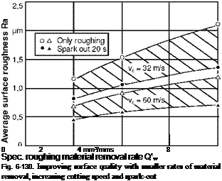
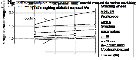
It has been shown which relations there are between the parameters and the output for single-stage processes. In these processes, a certain surface quality is to be allocated to each material removal rate at otherwise constant conditions. We can expect the best surface quality from the spark-out process. We thus obtain, as illustrated in Fig. 6-130, a range of obtainable surface qualities with the roughing process and the upper and the roughing process with spark-out as the lower boundary. The roughnesses lying within this range can be reached if a spark-out process is substituted for the finishing phase after roughing.
With the help of this characteristic diagram, we can estimate which roughing material removal rates are possible in order to obtain a desired workpiece quality taking into consideration the roughness improvement possible in the finishing phase. The relations in Fig. 6-97 refer to a constant material removal. Various cutting times may result as a function of the material removal rate; however, the influence of the machining time at constant material removal rate is not taken into account.
Therefore, the obtainable surface roughness is plotted in Fig. 6-131 as a function of material removal during roughing. The upper and lower limits result in turn from the pure roughing treatment/from the spark-out process. In between are values for various finishing conditions. For all conditions, roughness increases with material removal. The smallest increase the largest during roughing and the smallest during spark-out.
 |
After the described limit criteria have specified an area of operation, the working point that is most optimal with respect to cost and time must be found, as in single-stage processes. With respect to the described course of multi-staged processes in external cylindrical peripheral plunge grinding however, there is still a series of further factors to be considered.