The input variables of the grinding process determine the process parameters and the grinding results to a decisive degree. A continuous chip removal is guaranteed according to DIN 6580 by the coordination of the cutting motions and the infeed motion. The infeed motion can be composed of several components. Moreover, in some methods, a depth setting motions is also involved, which can also be conceived as incrementally executed components of one infeed motion.
The infeed radial, tangential and axial to the grinding wheel is represented by the variables fr, ft and fa. The depth of cut ae designates the depth setting motion in the working plane, while the contact width ap is perpendicular to this. The contact
infeed af points in the direction of the infeed motion of the grinding tool. Technological regularities are described with the help of systematics forming the basis for external and surface peripheral plunge grinding but which simultaneously can be used to describe other methods.
The Influence of the Depth of Cut ae
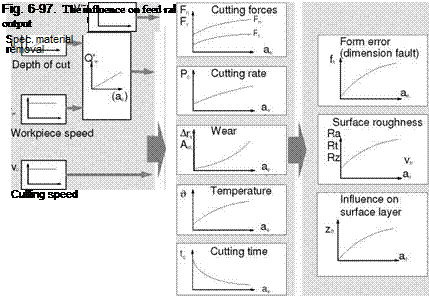 |
In Fig. 6-97, the influence of the depth of cut on process parameters and the result has been qualitatively represented.
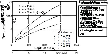
With an increase in the feed rate/depth of cut, an increase in the cutting forces results from the higher chip thicknesses and increasing kinematic cutting edge number. The experimental results for surface and external cylindrical peripheral grinding shown in Figs. 6-98 and 6-99 illustrate the degressive increase of normal and tangential force [GUEH67].
The momentary cutting number increases with the depth of cut due to the rising contact length. The chip cross-sectional area and thus the load on each grain also goes up with the depth of cut. Since the total forces are calculated from the sum of the forces on the particular cutting edges, and both the number of cutting edges being engaged and the load on the grains are increasing, the total forces must also increase.
|
□7 * ■ • |
 |
0 15 30 45 60 75 90 mm3/mms 120
Spec. material removal rate Q‘w
Fig. 6-99. The influence of the material removal rate and cutting speed on the specific normal force
Wear on the grinding wheel is also dependent on the material removal rate. We have already seen in chapter 2 how essentially two wear mechanisms are responsible for this.
• The dulling of individual grits by mechanical abrasion, adhesion, corrosion, diffusion as well as by microcracks and fractures caused by thermal stress.
• Break-out of entire abrasive grains or grain groups from excessive strain on the bond or from thermal or chemical wear on the binder.
Only the interaction of both of these types of wear characterises the wear behaviour of a grinding wheel. We speak of a “self-sharpening effect” if dull grains fall out of the bond at the right time due to the higher effective force, liberating new grains.
The radial wear speed Ars is variable for comparing the wear behaviour of a grinding wheel. As opposed to radial wear, which is assigned to an amount of material removal, the duration of stress on the grinding wheel, which varies with the specific material removal rate Q’w, is also involved in ATs.
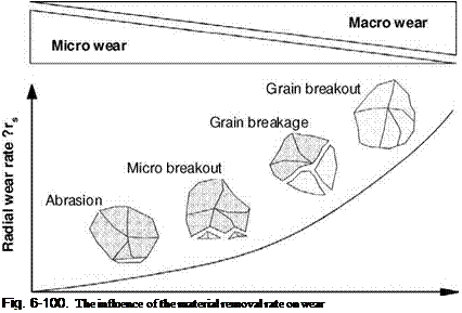
Fig. 6-100 shows the influence of the specific removal rate on the radial wear speed and the forms of wear thus appearing [BIER75]. At relatively low material removal rates, manifestations of micro-wear form due to the high specific thermal and mechanical stresses, leading to a pressure softening of grain tip. This can lead in turn to flat grit surfaces and thus to a reduction of cutting power [PEKL96]. At higher Q’w, wear behaviour is primarily determined by increasing mechanical stress. Depending on the material removal rate, splitting-off of crystal groups, break-out of grit parts or, in case the bond strength is exceeded, break-our of entire grains can occur [PEKL58a].
 |
Spec. material removal rate Q’w
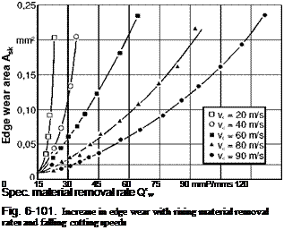
In the case of external cylindrical peripheral plunge grinding, the profile of the grinding wheel is reproduced on the workpiece. Thus, edge wear is generally often the criterion for service life in this method. In investigations of the determination of the service volume (volume removed up to the point a given service life end has
been reached), the relation shown in Fig. 6-101 between the edge wear area Ase and the material removal rate was found.
A 80 L 7 V Workpiece Ck 45 N Grinding parameters q = 60
Vw = 500 mm3/mm Cooling lubricant
Oil
Varying results can be found in the literature regarding the height of the temperatures appearing during the process and their effect on the output [LOWI79]. This can be partially derived from the fact that both the absolute temperature height in the contact zone as well as heat development processes in layers near the surface are difficult to obtain. For this reason, the temperature in the workpiece is given primary significance. The fact that the duration the heat action time is also important for the thermal stress on the external zone is ignored.
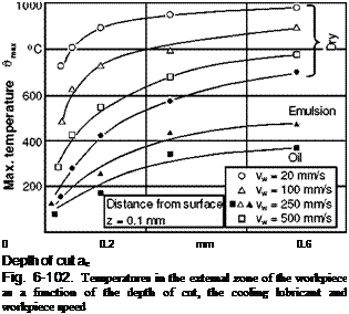
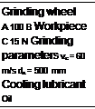
Temperature in the workpiece is dependent first and foremost on the cutting power, since up to 80 % of the cutting power flows into the workpiece as heat. The temperature increase in the workpiece associated with rising depths of cut can thus be attributed to the increase in cutting power/tangential force (Fig. 6-102).
Errors in form and dimension occur in grinding primarily from high cutting forces and grinding wheel wear and thus vary with respect to their mechanisms of origin. The profile accuracy of a workpiece depends for example on wear, errors in roundness on the other hand on the deformation of the total system and thus on the cutting force. One must therefore check which process parameter is responsible for each form and dimensional fault [BOET79].
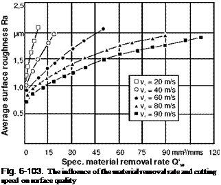
With increasing depths of cut/feed rates, the surface quality of the workpiece worsens [GUEH67, HOEN75, KOEN75, SALJ55, SPER70]. Fig. 6-103 shows the degressive increase in the average surface roughness Ra with the specific material removal rate. The increasing roughness is attributable, like the cutting force, to the chip thickness, which increases with the material removal rate. We can thus ascer-
 |
 |
tain basic agreements between the developing of the cutting force and of surface roughness.
A 80 L 7 V Workpiece Ck 45 N Grinding parameters Vw = 500 mim/mm q = 60
Cooling lubricant Oil
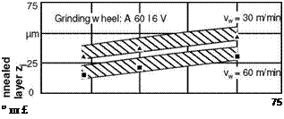
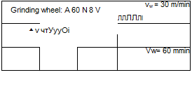
Finally, Fig. 6-104 illustrates the effects of the material removal rate on surface layer. Corresponding to the heat development increasing along with the material removal rate and the climb in temperature associated with it, the depth of the in
fluenced surface layer also increases. As a result of this structural influence, the hardness of the surface layer also changes.
In the case at hand, a reduction in hardness with increasing material removal rates was found. Apparently the thermal stress brought forth by increasing material removal rates exerted an annealing effect on the hardened base material.
100 Cr6 V Grinding parameters Vc = 30 m/s Cooling lubricant Emulsion (3%)
Fig. 6-104. The depth of the annealed surface layer for various grinding conditions
The Influence of Cutting Speed
Fig. 6-105 provides an overview of the relation of the process parameters and output to the cutting speed.
Raising the cutting speed has a positive effect on the cutting forces, mechanical wear and surface quality [ERNS65, KASS69, LOWI79, WERN71].
However, problems also occur when high cutting speeds are used, e. g. higher thermal stress on the workpiece and the necessity of increased safety measures. High-speed grinding is utilised either as a high-performance grinding method in order to shorten the machining duration at consistent quality or as a quality grinding method in order to improve the workpiece quality at constant material removal rate.
If the cutting speed is increased at a constant material removal rate, the advantages are reduced cutting forces, fewer shape errors as well as a larger cutting ratio and improved workpiece roughness. Increasing the cutting speed leads however to an increase in cutting power, which can lead to an increase in heat energy in the workpiece and thus to thermal damage to the component. If the goal of high-speed grinding is an increase in productivity, this can be achieved by simultaneously increasing the material removal rate with constant workpiece quality.
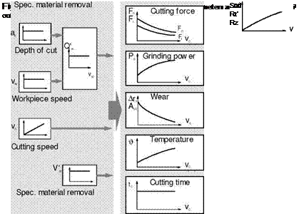 |
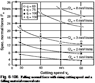
Fig. 6-106 shows the decline of cutting force with higher cutting speeds for various material removal rates. This decline can be attributed to falling chip crosssectional areas as well as to the smaller kinematic cutting edge numbers. The graphs can be flatter or steeper depending on the workpiece material.
Cutting power is the product of tangential force and cutting speed. Since both tangential and normal force become smaller with higher cutting speeds, the course of cutting power depends on whether the cutting speed increase can compensate for the loss of cutting force. In praxis, cutting power basically goes up with an increase in cutting speed. The theoretical borderline case Pc=Pc(vc)=konst. does not occur in praxis.
Higher cutting speed lead to fewer radial and edge wear (Fig. 6-107). Because of the reduced chip cross-sectional area, mechanical stress on the grinding wheel is also lessened. Growing frictional speeds as well as the engagement frequency are often overcompensated by the lower contact pressure and the shorter engagement durations [KASS69, SPER70, WERN71]. In exceptional cases, grinding wheel wear can increase again due to high thermal stress when a certain speed is exceeded. This is especially true for grinding wheels bonded with synthetic resin [KOEN71].
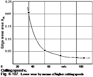 A 60 L 6 V Workpiece Ck 45 N Grinding parameters Vw = 300 mm3/mm Cooling lubricant Emulsion (17%)
A 80 L 7 V Workpiece Ck 45 N Grinding parameters q = 60
Q’w = 8 mm3/mms Vw = 500 mm3/mm Cooling lubricant
Oil
The increase in cutting power together with the cutting speed leads to higher temperatures (Fig. 6-108). At the same time, various cooling lubricants have an effect both on the maximum temperature and on the increase in temperature [DEDE72, MALK76].
The reduction of errors in form and dimension is to be attributed to cutting forces, which become smaller with higher speeds, as well as to reduce grinding wheel wear. When a service life criterion is specified, profile accuracy for example, the tool life can be increased by raising the cutting speed.
A 100 P B Workpiece
C 15 N
Grinding
parameter
Q’w = 10 mm3/mms Vw = 100 mm/s ae = 0.1 mm ds = 500 mm
Fig. 6-108. Lower cutting speeds and good lubrication reduce the workpiece temperature
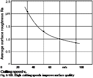
As Fig. 6-109 illustrates, the roughness of the workpiece surface drops with higher cutting speeds [ERNS57, ERNS65, KASS69, SPER70, WERN71]. The causes here as well are the smaller chip cross-sectional areas, which appear despite sinking kinematic cutting edge numbers.
A 80 L7 V Workpiece Ck 45 N Grinding parameters q = 60
Q’w = 8 mm3/mms Vw = 500 mm3/mm Cooling lubricant Oil
Corresponding to the higher temperature in the contact zone, the depth of the influenced surface layer also increases with the cutting speed. Here too, material — specific properties, e. g. heat conductivity, must also be taken into consideration.

