Gear honing is a finishing method for gears which was originally employed after grinding in order to produce surface structures on the tooth flanks favourable to noise emission. Small stock allowances of about 15 pm would be removed from the flanks. As the process developed further, it was able to be utilized directly after hardening, eliminating grinding from the process chain. As opposed to grinding, gear honing works with low cutting speeds (0.5 to 10 m/s), so thermal damage to the machined gears can be eliminated. On the contrary, internal pressure stresses are induced in the tooth flanks, which has a positive effect on the component’s load capacity [KOEL00].

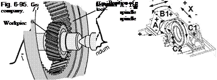
In principle, the gear-shaped tool can have external or internal teeth. Due to the superior overlay and the resultantly lower tool wear, gear honing with internal gear tooth tools are used industrially (Fig. 6-95).
During the process, the tool (honing tool) and the workpiece (gear) rotate synchronously. In addition, the rotation axes of both of these intermating partners are offset from each other by the so-called axis cross angle. By means of the generating motion and the axis intersection angle, there is a relative speed between the grains and the flanks of the workpiece. The tool is brought into proximity with the workpiece by the depth setting motion of the machine at high speeds. by means of which a high pressure is exerted on the grains in the tool teeth. In this way, material is removed from the workpiece flanks.
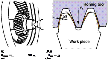
The maximum cutting speed vx possible in gear honing is limited by the capacity of the tool and by machine rigidity. However, there are also further dependences on the tooth number ratio between the tool and the workpiece and the resultant gear ratio. In order to quantify the performance of the tool at varying tool tooth numbers, the specific depth of cut per tool rotation ae, hon has proven to be the most useful technological parameter for describing the honing process (Fig. 6-96).
The machining duration of one workpiece is proportional to the stock allowance to be honed and inversely proportional to the relative depth of cut aeihon.
Machining situation Technological parameter
 |
Infeed per workpiece revolution
Fig. 6-96. Technological parameters in gear honing
In the case of dressable tools, the honing tool consists of a synthetic resin or ceramic bond, into which the grits (made, for example, of precious corundum, sintered corundum or cBN) are embedded. The honing tool can also be designed as a steel body on which the cBN or diamond grains are galvanically bonded.
To clean the honing tool, a fluid honing oil is sprayed on the teeth of the honing stone by means of adjustably arranged nozzles. The honing oil rinses chips and broken-off abrasive grains away from the machining zone.
Shortly before the final size is obtained, the NC-axes are controlled synchronously. In this way, surface quality can be improved on the one hand, and on the other defined crownings can be produced.
The honing tool is profiled both before machining the first workpiece of a new series as well as in the case of wear. First, the tip diameter of the honing ring is shortened with the help of a diamond dressing roller. After dressing the tip, the tooth flanks of the honing ring are dressed with a diamond dressing gear wheel. Its motions correspond to those of the honing cycle. However, dressing speeds are much lower than honing speeds. The amount of honing stone material removed is compensated automatically by the machine [BAUS94].
The diamond dressing gear wheel consists of a hardened steel body covered with diamond grains bonded in nickel. This diamond dressing gear wheel contains all required corrections, e. g. tip reductions, base reductions, conicity, crownings and topological corrections. By re-grinding after coating, irregularities of the diamond wheel coating are reduced, and changes to the modifications can be ground in to a small extent.
