
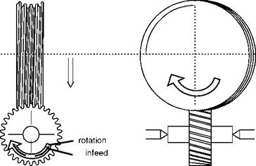
In continuous profile grinding, a globoid-shaped grinding worm serves as the grinding tool. As opposed to continuous generating gear grinding, the globoidshaped grinding worm does not have a tooth rack profile as its reference profile, but rather the contour of a tooth flank. Since we are dealing with a profile grinding process, contact between the grinding wheel and the tooth space approximates linear contact. These altered engagement conditions lead to fundamentally different kinematics than in generating grinding. Depth of cut and infeed correspond to each other, whereby a gyratory feed motion between the tooth flank and the globoid grinding worm occurs. A stroke motion in the direction of tooth thickness is generally not required since the contact areas between the gear and the globoid grinding worm are present across the entire width of the gear. Therefore, cutting across the width of the grinding wheel is guaranteed. The shifting used in continuous generating grinding to increase the tool’s service life cannot by carried out in continuous profile grinding (Fig. 6-92).
![]()
|
|
|
|
 |
|
|
|
|
![]()
![]()

![]()
![]()
The gear is exactly aligned in its rotational position with the help of a precentring and main centring finger (above right). The tool is connected with the tool spindle by means of a carrying device. Then the operating speed of the gear is synchronised with that of the grinding worm by means of an electronic measuring system. After adjusting in rapid operation to the full profile depth of the gear, the grinding gear is centred exactly in the central position of the tooth space (1, 2). In order to avoid penetration of grinding worm and gear, the tooth space profile has a slight undersize in comparison with the grinding worm profile.
The machining cut occurs in accordance with the so-called rotational feed method by means of a precisely defined rotary motion with overlaid infeed. During roughing, the rotational/cutting speed is raised accordingly in comparison to subsequent smoothing and sparking out (3, 4, 5). In this way, first the tooth flanks of one side are machined before the flanks of the other side are processed by turning back the gear by twice the angle number (6, 7, 8, 9). The machining process end with turning the gear into the centre of the space and its subsequent emergence from the tooth space into the exit position (10, 11, 12).
Since in continuous profile grinding the profile of the target tooth flank and the profile of the globoid grinding worm are approximately identical, the grinding worm is tool-bound. This necessitates, as in discontinuous profile grinding with galvanically single-coated tools, that each type of gear has its own tool. As opposed to discontinuous profile grinding, only conventional grinding wheels are used, dressed with a profiled dressing tool. The contour of diamond-coated dressing tools exhibits a similar contour as the gear that is later to be ground. Thus the flexibility of this method is clearly limited due to the high costs of the dressing wheel, which is why it is almost exclusively utilised in large batch production.
Fig. 6-94 shows the workspace of a machine used for continuous profile grinding. The centring fingers are arranged below the driveshaft clamped by a internal spring chuck and the opposing tip. The grinding support is adjusted radially with the grinding worm. The dressing tool is driven into the tool position for the profiling process by means of an additional axis and is clamped accordingly.
The applicable machining parameters for continuous profile grinding are, in roughing, limited by structure influences as a result of the high grinding power and resulting increase in heat in the tool. In finishing, the given permissible surface roughness of the flanks limits the material removal rate. The end of the tool’s service life (the duration between two dressing cycles) is determined either by an unallowable reduction in gear quality as a result of profile-form wear or insufficient grinding worm cutting power, leading to textural influence on the tool or to increased deviation of the flank line.