
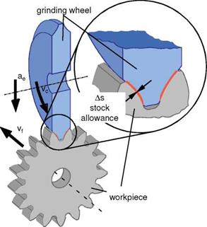
Fig. 6-88 is a schematic representation of profile grinding of an external gear tooth spur gear. The grinding wheel exhibits the profile of the tooth space in transverse section. The grinding wheel profile is transferred to the tooth flank by the depth of cut ae in the radial direction corresponding to the decreasing stock allowance and a subsequent axial treatment with speed vf in the direction of tooth thickness. Since the grinding wheel form depends on the workpiece, any change in gear geometry, such as a profile modification of the tooth flank or machining the gear with other geometry data, requires a correspondingly profiled grinding wheel.
In industry, dressable and galvanically bonded cBN grinding wheels are used. These grinding wheels, due to their large grain projections and the high wear resistance of the cBN grains, permit high material removal rates and service lives. The facts that they cannot be shaped and the resulting lack of flexibility however limit the use of galvanically bonded grinding wheels primarily to the manufacture of large batches.
By using dressable grinding wheels there is the possibility of altering the profile of the grinding wheel by means of a dressing process [BAUS94, BOUC94]. In order therefore to make the manufacture of smaller batch sizes by means of discontinuous profile grinding economical as well, tooth flank profile grinding machines with an integrated dressing unit have been available for some time. The
profile of thereby engaged ceramically bonded grinding wheels are created by generating the involute profile with a diamond form roller.
|
Fig. 6-88. Discontinuous tooth flank profile grinding in dual-flank section |
In tooth flank profile grinding, two different stock distributions are used depending on the process strategy selected. The most frequently applied process in industrial praxis is radial stock distribution (Fig. 6-89, right). In this method, the grinding wheel possesses the profile required to achieve the final geometry and machining occurs in several radial cuts. Here, a two-flank treatment is possible, which is advantageous with respect to machining durations. The disadvantage of this strategy is that the grinding wheel makes contact only with the root flank in the initial grinding strokes. The stock allowance in the area of the tip flank and the tooth root fillet is only ground in the last few strokes, so the risk of grinding burn is especially high here. Moreover, modifications of the flank line across the width of the gear are realised by moving the grinding wheel radially. In this way, deviations of the profile geometry from the target geometry occur on the faces of the gears.
If these deviations are to be avoided, the grinding process must be executed with a single flank. For this, the grinding profile must be dressed thinner, i. e. a larger addendum modification (profile displacement?). The cutting motion is executed by means of a rotation of the workpiece. In this process strategy, an equidistant stock allowance is ground across the profile height of the gear (Fig. 6-89,
left). This process strategy however has a negative effect on machining durations, since both flanks must be ground separately.
Equidistant stock distribution Radial Stock distribution
 _ ^ ‘■n (ae = const.)
![]()
![]()

 1st cut cycle 22nd cut cycle,3rd cut cycle
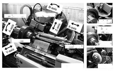
Fig. 6-90 shows a profile grinding machine with an integrated dressing unit for tooth flank profile grinding. Cutting of the workpiece occurs along the Y-axis with the workpiece carriage, upon which is mounted the semi-automatic unit with the mandrel and the gear (A-axis). The axial feed motion is realised by moving the grinding support in the X-direction. The Z-axis serves to position the grinding wheel and component axis on one level. In the case of angle-serrated spur gears, the B-axis is pivoted around the helix angle of the gear before machining. Additionally, during the machining process, the gear (A-axis) is rotated in conjunction with the X-axis in accordance with the helix angle. During dressing, the contour of the grinding wheel is created by implementation of the X — and Y-axes, whereby the dressing roller and grinding wheel axes are level with each other (Fig. 6-90, right).
In profile grinding, there are complex contact areas between the grinding wheel and the workpiece in transverse section, as Fig. 6-91 illustrates for the treatment of an angle-serrated spur gear. In the upper part of the picture, the contact between the grinding wheel and the tooth space is shown for a particular depth of cut. The dimensions of the engagement surface is relatively large, whereby the boundary of the contact zone has a complex formation due to the transition from the involute profile to the root of the tooth space. The machining rates vary along the tooth height and width. To clarify this, the tooth space has been unwound into one plane
 in the lower half of the illustration. In the rear areas of the tooth space and at the tooth tip, no cutting is momentarily taking place. The individual machining values can be read from the flank outline and the tooth width as a function of the path. In general, removal decreases across the flank outline for both tooth flanks from tooth tip to the transition from tooth flank to root, while at the tooth root the maximum material removal rate is reached after a clear increase. In the direction of tooth thickness, removal is largely constant. In the exit area of the grinding wheel, the material removal rate is drastically reduced.
Grinding
B»’ —
Meausring
‘■ ; sensor
![]() gear
gear
dressing unit
![]() Dressing і
Dressing і
Fig. 6-90. Tooth flank profile grinding machine with an integrated dressing unit front the Kapp company
Profile grinding is particularly effective in comparison to generating methods. However, the large contact zones at high material removal rates and the high heat levels in the workpiece associated with this demand sufficient cooling lubricant supply in the grinding gap. The material removal rate of tooth flank profile grinding is limited primarily by the grinding power and heat increase and the grinding burn damage resulting from it. As opposed to generating methods, the removal rate (feed rate, depth of cut) has only a minor influence on gear quality. The service life end of the grinding wheel is reached, on the one hand, due to insufficient cutting power of the abrasive coating caused by wear, which in turn leads to influences on the material’s structure. On the other hand, profile-form wear of the grinding wheel signals the end of service life if permissible deviations from the target profile of the tooth space are exceeded and gear quality can thus no longer be maintained [BAUS94, BOUC94].
boundary of the contact zone line contact
boundary of the contact zone. stock removal