
 |
In the case of continuous generating gear grinding, the tool used is a grinding worm with an exact gear rack profile (Fig. 6-84). The grinding worm and the gear are each driven by a separate synchronous reaction motor. The involute form arises by continuous rolling of the grinding worm and the gear. The process is not interrupted by subprocesses. The rolling motion is superimposed by an axial feed of the workpiece carriage. This feed causes the formation of the gear in the direction of the tooth flank and can be regulated smoothly within definite limits. The depth of cut takes place gradually at the upper and lower reversal points of the axial motion. Furthermore, there is the possibility that the workpiece can be shifted tangentially in order to exploit the grinding worm more effectively. This corresponds to the shift motion in hobbing.
Fig. 6-84. Process input parameters in continuous generating gear grinding
In continuous generating gear grinding, the material removal rate is restricted primarily by the realizable gear quality and not by the appearance of grinding damage. Since no subprocess takes place, individual pitch variation is very small. In this method, profile-form deviation is the main factor in gear quality.
Fig. 6-85 delineates the flank topography of a tooth space ground with continuous generating gear grinding. The considerable increase in profile-form deviation ff with increasing axial feed is partially contingent on the infeed markings (Fig. 685, left diagram).
Fig. 6-85. Increase in profile-form deviation with increasing axial feed in continuous generating
gear grinding
The right part of Fig. 6-85 shows the involute diagrams of gears ground with different feeds. The cause for the characteristic profile-form deviations (a groove in the middle of the involute) lies in the contact conditions between the grinding worm and the gear.
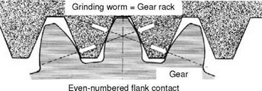
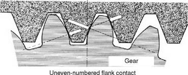
In the transverse section of the gear, the grinding worm can be represented as a tooth rack, as can be seen in Fig. 6-86. With an even number of contact points (Fig. 6-86, above), an equal amount of contact points lie on the left and right flanks, so that there is a largely uniform distribution of force. If the amount of contact points is odd (Fig. 6-68, below), the distribution of force is imbalanced, which can lead to a characteristic profile-form deviation. The type of flank contact is determined by the tooth geometry, i. e. by the module, tooth number, engagement angle and helix angle, as well as by the number of threads the grinding worm has.
The material removal rate is determined by the grinding worm thread number, the grinding worm speed and the remaining machine input parameters. The relation between the variables and grinding burn is depicted in Fig. 6-87.
|
|
|
Fig. 6-86. Contact conditions in continuous generating gear grinding |
Above right in Fig. 6-87, the percentile amount of grinding burn area on the tooth flank as a function of the axial feed and depth of cut is plotted. According to expectations, most grinding damage is seen with higher feed and depth of cut amounts, whereby grinding cracks do not generally appear. To what extent other changes besides visible grinding damage exist, such as hardness reduction in the workpiece external layers, is shown in Fig. 6-87, below. Upon it is plotted the Vickers hardness HV 0.3 over the distance s of the workpiece boundary for one gear respectively with light grinding burn (about 20 % area proportion) and with considerable grinding burn (about 50 %). For a tooth flank with extensive grinding burn, hardness clearly declines. This influences the load capacity of the gear. In the case of a tooth flank with light grinding burn, the measured hardness is scattered considerably, due to the very low test force, so that a reduction in hardness on the workpiece surface could not be clearly determined.
 |
Fig. 6-87. Grinding damage in continuous generating gear grinding