
Discontinuous Generating Gear Grinding with two Disc Grinding Wheels
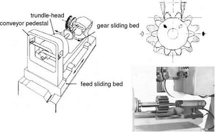
The hobbing engagement for producing an involute profile is transferred by means of a construction of rolling motion blocks and conveyor belts (Fig. 6-75). This method is used to produce higher gear qualities (up to quality 2 according to DIN 3961 [DIN78]) and complex gear modifications. The maximum material removal rates that can be reached are low because of the rolling kinematics and the associated theoretical point-contact between the workpiece and the tool in transverse section. From the low permissible material removal rates result low cutting forces, so that machining is possible without cooling lubricant.
|
Fig. 6-75. Discontinuous generating gear grinding with two disc grinding wheels (Maag) |
Discontinuous Generating Gear Grinding with a Double-Tapered Wheel
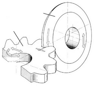
In discontinuous generating gear grinding with a double-tapered wheel, the production of the tooth shape is based on the rolling principle between the gear and the gear rack. The grinding wheel has a trapezoid-shaped cross-section and thus corresponds to a singe gear rack tooth. By means of the hobbing engagement of the workpiece on the straight flank of the grinding wheel, an exact involute is created (Fig. 6-76).
 vroll
vroll
Fig. 6-76. Process input parameters in tooth flank profile grinding with a double-tapered wheel using the discontinuous generating gear method
In the case of angle-serrated spur gears, the grinding wheel is swivelled in accordance with the tooth inclination angle at hand. The grinding wheel produces the involutes by grinding the tooth flanks along the straight production lines. These lines correspond to the contact lines in the coupling of two gears. Fig. 6-77 shows the process.
The attainable material removal rate in partial generating gear grinding is limited by the appearance of thermal external zone damage. This can be avoided by the right choice of process input parameters. Since discontinuous generating gear grinding with double-tapered wheels is comparable to flat grinding, we will first explicate the relation between the variables and the temperature in the workpiece in flat grinding.
The upper diagram in Fig. 6-78 shows the influence of workpiece speed on the temperature of the workpiece. The region of feed rates, as they are utilised in discontinuous generating gear grinding with a double-tapered wheel, are shaded in grey. The diagram shows the small influence of feed rate on the temperature of the workpiece in discontinuous generating gear grinding. The depth of cut on the other hand, particularly in the region of values common in discontinuous generating gear grinding, influences the workpiece temperature very strongly (Fig. 6-78, below). However, transferring the results of flat grinding to discontinuous generat
ing gear grinding, we must pay heed to the differing process kinematics of both methods. While the material removal rate in flat grinding is constant due to consistent values for the depth of cut ae, grinding wheel engagement width bs eff and workpiece speed vw, in discontinuous generating gear grinding this varies according to the tooth flank height and width. The result is that, besides the depth of cut, the current rolling position is of considerable influence upon the local material removal rate.
|
Fig. 6-77. Process run in discontinuous generating gear grinding with a double-tapered wheel during single flank grinding (Hotter) |
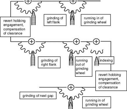
Fig. 6-79 shows the derivation of the specific material removal rate for discontinuous generating gear grinding in a rolling position of the grinding wheel. The material removal rate results from the product of the chip cross-sectional area Acu, which is nearly triangular due to the method’s kinematics, and the tangential feed rate vft erpendicular to it.
Since the feed motion in discontinuous gear grinding machines is frequently created by a crank mechanism, the non-constant progress of the feed rate shown in Fig. 6-79 appears across the tooth flank width.
|
CD 1— 3 +-» rc 1— CD Q. E CD 4-* X (0 |
|
CD 3 4-* (0 a> E a> 4-* X (0 |
 |
 |
Fig. 6-78. Relation between machine input data and workpiece temperature in flat grinding (Dederichs)
The chip cross-sectional area varies due to the kinematics of rolling and the involute profile along the tooth height. At the head of the tooth flank, the larger workpiece diameter leads, at the existing constant angle speed of the machining wheel, to a higher rolling speed than at the foot of the tooth. This distance of the
individual engagement lines of the grinding wheels and thus the chip crosssectional area are thereby increased. In addition, the engagement angle of the involute profile varies along the tooth height. This also causes a change in the chip cross-sectional area as a function of the tooth flank height.
Fig. 6-80 portrays the effect of both of these partially compensating influences on the existing chip cross-sectional area along the tooth height from the head to the foot. The largest chip cross-sectional area is at the tooth height at the thirty — second stroke. If the individual chip cross-sectional areas are added, we obtain the total chip cross-sectional area across the active grinding wheel area (Fig. 6-80, above). In order to reach higher material removal rates in discontinuous generating gear grinding, besides varying the machine input parameters, a suitable choice of grinding wheel composition and conditioning as well as of cooling lubricant is also possible.
Fig. 6-81 shows the maximum permissible depth of cut at which no damage ensues plotted across the rolling speed and the number of return strokes. The permissible parameters lie beneath the given boundary surface. In the case of parameters above this boundary surface, damages to the gear are to be expected [KOEN76, KOEN77, KOEN79, KOSC76, MEIJ79].
In the case of discontinuous generating gear grinding with a double-tapered wheel, problems arise with respect to gear quality mainly due to profile-form deviation and the pitch error. The pitch error is essentially dependant on the pitch
accuracy of the grinding machine. Fig. 6-82 explicates the deviation arising from the process.
16MnCr5
mn = 6 mm; z = 15
b = 15 mm; a = 20° в = 10° right x = 0,5
quench hardening 860 <C/Ol
EHT550 = 0,7 … 1,0 mm
EK 60 G8 Ke vs = 30 m/s
grinding oil
While the rolling motion progresses continuously, the grinding wheel performs a working stroke along the tooth flank. In this way, the profile of the tooth flank is not formed precisely as an involute but by means of a finite number of profile cuts as a polygon, and only the points of the profile cut lying on the contact path of the generatrix are in the theoretical involute profile. The distance between the penetration of two profile cuts and the theoretical involute is the profile-form deviation caused by the process. Fig. 6-83 shows the resulting involute surface. Deviations of the actual flank surface from the ideal involute surface are represented exaggeratedly, such that the straight lines of the polygon are distorted as parabolas. The largest deviations are at the tooth head.
The lower part of Fig. 6-82 shows the path of process-induced profile-form deviation in the direction of the generatrix. At the end of the stroke, the fault is almost four times that of the middle of the stroke. A sensible choice of overrun path makes it possible to limit this error. In discontinuous generating gear grinding, the machine input parameters return-stroke number iRS, rolling speed vroll and depth of cut ae are selected from two points of view. The first is gear quality, and the second is the avoidance of grinding damage.
 |
Coolant lubricant simple curing 860 °C/Ol grinding oil Eht550 = 0,7 … 1,0 mm
Fig. 6-83. The determination of optimal machine input data with respect to quality and machining duration in discontinuous gear grinding with a double-tapered wheel
Fig. 6-83 illustrates the relation between gear quality, material removal rate, machining duration and roll speed for one gear example.
At low roll speeds, the profile-form deviation is smallest and the maximum allowable depth of cut the largest. Although the time per circuit is relatively high at low roll speeds, by means of a large depth of cut, the number of circuits can be reduced such that by conserving part-times the machining duration decreases with diminishing roll speed.