6.3.5.1 Kinematic Fundamentals
 |
According to DIN 8589 [DIN78a], there are many different variations of belt grinding, of which only the most important are indicated in Fig. 6-64. The main factors in classifying them are on the one hand the position of the feed motion characterising the method, and on the other the contact element (roller = peripheral grinding; shoe = side grinding).
Fig. 6-64. Belt grinding methods according to DIN 8589 [DIN78a]
If a contact wheel is used, the particular methodological variations then correspond to those in grinding with a grinding wheel (see chapter 6.3.1). The kinemat
ics of peripheral belt grinding processes also correspond to those of grinding with grinding wheels. For machining operations with contact shoes, the same kinematic data are pertinent, except that in this case the influence of the respective grain paths is to be considered as a function of the supporting element geometry.
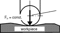
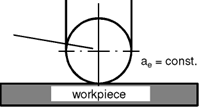
The belt methods most frequently employed use a contact wheel or shoe. We will therefore explore these methods in more detail. Both methods are based on different procedures which vary decisively with respect to their process parameters (Fig. 6-65).
![]()
grinding with constant
contact force
grinding with constant
depth of cut

|
|
|


• Real depth of cut is the set depth of cut
• True to dimension grinding.
• Form grinding must be done
• by machine control.
Fig. 6-65. Varying procedures in belt grinding
One belt grinding variant is the oft-used grinding with constant contact force, which is employed in order to refine the surface or to machine large material volumes per time unit. With this procedure, uneven components can also be machined, whereby the constant grinding pressure assures that comparable allowances are removed on the entire workpiece surface. The disadvantage of grinding with constant contact force is that one cannot grind to size. This is the case when grinding with constant depth of cut, where high formal and dimensional precision have to be realised at constant material removal rates.
In order to understand the relations between the variables and the parameters and the output, basic considerations concerning the wear mechanisms involved in
abrasive belts is required. As opposed to grinding wheels, the individual grains of the abrasives on backing material are completely imbedded in the bond material and thus have a high break-out resistance [DENN89]. For this reason, grain breakout is rare in belt grinding, whereas splintering and grain blunting are more common. The latter results in an increase in friction, bringing about the danger of a thermal influence on the workpiece due to the increase in grinding temperature.
In belt grinding, an oscillation speed is often also superimposed to the circumferential speed. Its vector runs parallel to the produced workpiece surface and perpendicular to the cutting speed vector. By means of this cross motion, the paths of the individual grain cutting edges overlap. This produces a much improved component surface quality [DENN89]. Furthermore, the oscillation helps prevent the belt from coming off the driving roller as well as a more even wear of the belt.
Increasing the cutting speed with constant grinding force raises the material removal rate with diminishing surface roughness. At the same time, the grinding temperature and grain wear go up [VDI03]. An overview of cutting speeds for different materials is provided in table 6-1.
|
Table 6-1. Standard values for cutting speed as a function of the material [VDI03]
* for structured grinding belts |
