Surface or flat grinding serves to create surfaces that are either completely level or extend in the main feed direction of the grinding wheel in a straight line. Surface grinding comprises the methods of peripheral plunge, peripheral longitudinal, side plunge and side longitudinal grinding. In industrial practice, the most often utilised methods are
• peripheral plunge grinding (groove grinding or profile grinding) and
• peripheral longitudinal grinding (surface grinding or levelling large surfaces).
The principles of these methods are illustrated in Fig. 6-62.
In surface peripheral plunge grinding, the grinding tool is moved orthogonally to the machine table with the depth of cut ae and as a rule the table is moved at feed rate vw. For the specific material removal rate Q’w, the following is valid:
crosswise-grinding
traverse-grinding
|
Surface peripheral longitudinal grinding is used to create level surfaces with large lateral dimensions. The grinding wheel is moved orthogonally to the workpiece surface by the amount ae (Fig. 6-62). The grinding wheel is as a rule moved axially outside the workpiece by the amount ap which due to the process corresponds to the effective grinding wheel width bs eff. By changing the directions of the workpiece feed rate, the grinding mode is altered. In the case of up grinding, the speed vectors of cutting speed and workpiece feed rate are oppositely directed. The cutting edges of the grinding wheel’s peripheral surface penetrate nearly tangentially to the finished surface into the contract zone and leave the latter at the workpiece blank surface. In down grinding, the engagement conditions described are reversed.
The determination of the specific material removal rate according to equation 6.95 for surface peripheral longitudinal grinding is only acceptable under the assumption of a rectangular grinding wheel edge. As a result of grinding wheel wear during the process, the effective depth of cut ae for the feed element of the width ap illustrated in Fig. 6-62 is reduced by the amount of radial grinding wheel wear. The dimensional fault in the element of width ap, proportional to the size of the radial grinding wheel wear Ars, is compensated by the fact that in a newly executed cross feed, a region of the spark-out zone with the width of feed ap grinds off the remaining allowance from the previous stroke. With increasing material removals, a stepped wear profile thus results.
With this grinding method, components with large widths are machined in several cross paths, such that in general after each cross feed the cutting direction is switched. Now the other side of the grinding wheel is engaged, and on this side a corresponding stepped wear profile is also formed. In order therefore to determine exactly the specific material removal rate of a grinding wheel being engaged, the exact knowledge of the wear profile is necessary.
The area of the grinding wheel width bs (depth of cut ae = 0) not taking part in machining generates the workpiece surface and determines to a large extent the roughness of the workpiece. The parameter overlap ratio U in this context indicates how often an area of the surface is ground by a grinding wheel of width bs:
![]() U = і = A
U = і = A
ap fa
Higher number of grinding paths generally lead to low levels of workpiece roughness. An exact calculation of the number of grinding paths is, as described above, only possible with an exact knowledge of the wear profile of the grinding wheel.
 |
 |
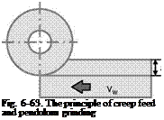
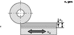
Fundamentally, one can use creep feed grinding or pendulum grinding in both variations mentioned (Fig. 6-63) [BRAN78]. In the case of creep feed grinding, the workpiece form is ground with large depths of cut, often even in one overrun from the solid. Since the specific material removal rate to chose is dependent on the existing grinding wheel-workpiece combination, the workpiece feed rate vw is adjusted inversely proportional to the depth of cut ae in accordance with equation 6-95. With increasing depths of cut, the contact length between the workpiece and the grinding wheel increases, making the transport of cooling lubricant into the contact zone and the removal of chips more difficult. For this reason, creep feed grinding uses on the one hand open-structured grinding wheels of low hardness and on the other an effective cooling lubricant supply (large volume flows at high pressures). The advantages of creep feed grinding as opposed to pendulum grinding are improved workpiece surface quality and lower grinding wheel wear. Creep feed grinding is used industrially especially in the final processing of exact shapes, e. g. guide tracks and clamp profiles of turbine blades. Moreover, as is shown in Fig. 6-63, grinding times are shorter than in pendulum grinding, as there is no time spent on free travel and table rerouting times.
The workpiece surfaces produced by creep feed and pendulum grinding have different reflection behaviours. pendulum-ground workpieces are characterised by a matt surface, while creep feed grinding produces a shiny one.

