
According to the process variant, a supersonic oscillation is superimposed in the contact zone either vertical or parallel to the workpiece surface in addition to the conventional cutting movement. This change in the speed ratios and in the resultant cutting speed leads to functional and wear mechanisms, which are basically different from those of conventional grinding.
20.2 PERIPHERAL GRINDING WITH RADIAL ULTRASONIC ASSISTANCE
Material removal and tool wear mechanisms of peripheral longitudinal grinding with radial ultrasonic excitation of the workpiece can be described through the simulation of the engagement of a single grain (Figure 20.4) and through scratch tests [Uhlmann and Holl 1998(b)].
If the feed speed is ignored, the path of a grain making a scratch, without ultrasonics, is described by the segment of a circle. The grain penetrates the material up to the depth of cut of the single grain, aeG-CON, with a constant wheel speed, vs, and a defined engagement angle, ae-CON. The maximum depth of scratch is reached at the lowest point of the curve. After leaving the surface, the grain has marked a trace of the length l Rt-CON.
Additional longitudinal workpiece vibration causes significant deviations in a radial direction from the path described before. Depending on how many workpiece vibrations are realized per contact phase, a number of single scratches locally strung together with different scratch depths and lengths emerge instead of a circular scratch. The maximum depth of scratch increases by the value of the amplitude at nominally equal single-grain working engagements. As long as aeG-CON is smaller than the amplitude, complete contact disruptions occur in each case between the local single-grain scratches. Due to the additional speed component in the radial direction, the grain hits the surface at a larger engagement angle with higher active speed. Each local single-grain scratch is characterized by distinctly shorter contact times and single-grain lengths of scratch, as well as higher single-grain depths of scratch.
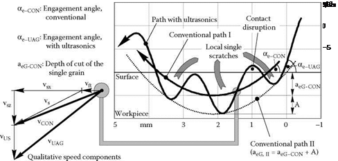 |
Figure 20.5 displays the surfaces of the materials, silicon nitride (SSN), and zirconium oxide (ZrO2) scratched with and without ultrasonic assistance at equal maximum depths of scratch.
|
FIGURE 20.5 Scratches on different ceramics with and without ultrasonics. |
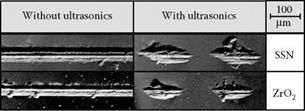
The wheel speed of the single-grain diamond was set to vs = 5 m/s. Scratching without ultrasonic assistance leads to continuous traces, which mainly display areas of plastic deformation on the bottom of the scratch, partly showing traces of other single cutting edges. Processes of material removal occur while the diamond grain moves from right to left, which, due to critical stress conditions, causes radial cracks on the scratch borders that run vertically to the direction of motion. Above this are a number of lateral cracks depending on the K/c-value, leading to conchoidal chips of material particles.
Observing the traces generated with ultrasonic assistance it becomes clear that the entire trace is divided into local single-grain scratches. Repeated contact disruptions are due to periodic oscillation of the workpiece as well as superimposed circular movement of the single grain diamonds. The effect of complete liftoff and re-entry into the workpiece surface was similarly noticed for all tested materials. The scratches are primarily characterized by plastic deformations. Lateral crack systems are formed on the right and left borders of the scratches in relation to the depth of indentation, resulting in conchoidal chips.
The effects of ultrasonically assisted grinding cause a higher mechanical load of material and diamond grits. In addition, the time of contact and, hence, the friction effects are distinctly reduced, thus decreasing the thermal loads. However, the degree that mechanical stresses appearing due to material displacement processes in front of the cutting edge are influenced remains unclear.
The theoretical center distance of two local single-grain scratches can be determined by approximation directly from the relation of wheel speed, vs, and oscillation frequency, f. A comparison of theoretical setting conditions with actually generated structures contributed to the verification of the formation of scratch geometries typical for ultrasonics [Spur and Holl 1997].
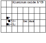
Figure 20.6 shows the resulting normal and tangential forces during creep feed grinding of silicon carbide, zirconium oxide, and aluminum oxide with and without ultrasonics. Ultrasonic assistance leads to a significant reduction of the process forces. Contrary to conventional creep feed grinding, the course of the process course is quasistationary. The ultrasonic superposition leads to higher stresses of the workpiece subsurface and the diamond cutting edges. Without ultrasonic assistance, the diamond cutting edges get flatter in the course of the process, starting from the sharpened state. Thus, the grain strain increases. Above a certain marginal load, the grain parts splinter in big segments or break-off. The grains have not flattened in any of the cases with ultrasonic assistance. Rather, an increase in microsplitting could be observed. If transferred to the grinding process, the microsplitting leads to a continuous generation of sharp single cutting edges. This results in the quasistationary state.
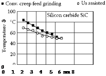
Figure 20.7 shows the integral temperature values in the subsurface of different ceramics during creep feed grinding with and without ultrasonics. The measurement of temperature values was carried out with thermal elements, which were positioned in the subsurface of the workpieces. It becomes clear that the superposition of ultrasonic leads to a significant decrease in temperature.
The contact interruption between wheel and workpiece as a result of ultrasonic oscillation leads to a reduction of engagement times as described above. Moreover, infeed of coolant at the contact
![]()
![]()
![]()
 60 a) a
40
OJ
H
20
0
![]()
|
|
|
|
 |
|
Grinding wheel: |
D126 K + 888 JY C50 |
|
KSS: |
Solution, 4%, p = 5 bar |
|
Material: |
SSN |
|
Cutting speed.: |
vc = 35 m/s |
|
Infeed: |
ae = 1 mm |
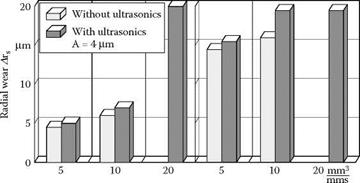
FIGURE 20.8 Radial wear of the grinding wheel and the surface quality of silicon nitride during conventional and ultrasonic-assisted down grinding.
zone is improved by temporary lifting of one of the active partners and by the removal of chips. The reduction of the friction effects reduce grain flattening and the preferred microsplitting of the diamond grains can be considered further reasons for the decrease of process temperature.
Figure 20.8 shows the radial wear of a grinding wheel and the surface quality of a silicon nitride ceramic. Just as in conventional grinding, radial wear of the grinding wheel increases in grinding with ultrasonics with increasing specific material removal rate. In the case of ultrasonic — assisted grinding, radial wear of the grinding wheel is higher than in conventional grinding. In the case of a material removal rate of Q’w = 20 mm3/mm/s, machining was not possible with a conventional process method due to inadmissible process forces.
Surface roughness also increases with specific material-removal rate in both process variants. In ultrasonic-assisted grinding, surface roughness is higher than in conventional grinding.