
19.14.1 Vibration Frequencies at Threshold Conditions
Figure 19.59 shows a stability threshold plotted against vibration frequency rn for n = 25.0 to n = 26.1. The vibration frequency for a dynamic stability threshold mainly lies just above the natural frequency (O0 of the main machine vibration mode.
Figure 19.59 has four distinct zones. These are shown as
• Absolutely stable. 25.0 to 25.8 waves.
• Absolutely unstable. 25.8 to 26.0 waves. Frequency range 1 to 1.7 xffl0.
• Conditional dynamic instability for high forces. Approximately 26.01 waves.
• Conditional dynamic instability for low forces. 26.01 to 26.1 waves.
In this example, it can be seen that care should be taken to avoid frequency ratios rn/rn0 in the range 1.0 to 1.7. For other conditions and number of waves, the range may be even larger.
19.14.2 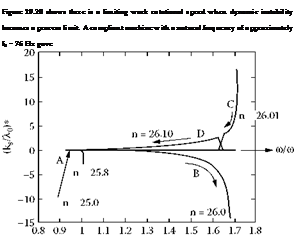
Selection of Work Rotational Speed
instability at work rotational speeds above nw = 4.5 rev/s. At this workspeed, the number of waves would be expected to exceed 76/4.5 = 17 waves.
The results for the very stiff machine presented in Figure 19.20 were for a natural frequency f0 = 500 Hz. Instability was experienced for workspeeds above 16 rev/s. At this workspeed, the number of waves experienced would be expected to exceed 31 waves.
31 or more waves will be attenuated by contact filtering more than 17 waves. These results explain why a very stiff machine allowed higher workspeeds to be employed and the smaller amplitude of roundness errors when the process became unstable.
If roundness problems are experienced with a particular workpiece diameter, it is necessary to determine the cause of the vibration. Frequency of vibration can be evaluated from the number of waves on the workpiece multiplied by the work rotational speed. This will assist in identifying the source of vibration and workspeed can be chosen to avoid a convenient waviness. If the frequency is identified with a machine resonance, the usual adjustment is to reduce workspeed.
Figure 19.20 shows that at low workspeed there is increased risk of thermal damage. If vibration is associated with a thermal damage condition at very low workspeeds, it is necessary to increase workspeed.
19.14.3 Selection of Grinding Wheel Rotational Speed
Problems can arise in any grinding process when the grinding wheel rotational speed is an integer multiple of the work rotational speed. This is because any wheel runout due to wheel unbalance or other cause will be imposed at the same positions on the workpiece in a repetitive action. For example, if the grinding wheel speed ns = 30 rev/s and the work rotational speed nw = 3 rev/s, it is probable that n = 30/3 = 10 waves will be detectable in the work roundness.
For similar reasons, wheel speed should not be allowed to lie at the same speed as the dominant natural frequency. Even direct multiples and submultiples should be avoided.