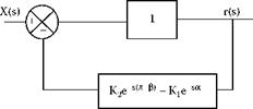
The geometric function Gg(s) as illustrated in Figure 19.45 represents an inner feedback loop in Figure 19.43.
The two feedback terms form circles when varying frequency. The larger circle in Figure 19.46(a) is the control wheel feedback and the smaller circle is the workrest feedback. If the two terms are added, the feedback locus is a spiral of approximate circles varying in size depending on the number of waves. Figure 19.46(b) shows the characteristic equation of the geometric function 1/Gg(j ■ n) for 16 to 18 waves. Encirclement of the origin indicates geometric instability for 16 waves.
Near the origin, the wave at the control wheel position is in antiphase with the wave at the grinding point. At the workrest, the wave is in phase with the wave at the grinding point as described in the earlier discussion on convenient waviness.
If the locus passes the origin on the negative side, waviness builds up because the feedback adds to the wave at the grinding point. This allows us to define a geometric stability parameter “A.” When A becomes negative the system is geometrically unstable. The parameter A represents feedback to the depth of cut in phase with the waviness. The imaginary part, “-B” represents feedback in quadrature with the waviness. Plotting these two parameters forms the locus 1/Gg (j ■ n).
Re = A = 1+K2 cos[n(n — в)] — K cos[na] (19.71)
Im = — B = K sin[na] — K2 sin[ n(n — в)] (19.72)
|
FIGURE 19.45 The geometric function represented as an inner feedback loop. |
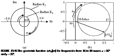
The plot in Figure 19.46 is negative for the unstable 16 waves but is slightly positive for the marginally stable 18 waves. The plot indicates a strong rounding tendency for n = 17.
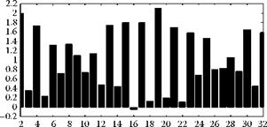
Figure 19.47 is a plot of the geometric stability parameter, A, against number of waves over the range of interest. Values are shown for a 10° tangent angle and a 20° workrest angle for up to 32 waves. This plot allows geometric stability at all the frequencies to be investigated. It appears there are several instabilities over the range. The most serious is at 16 waves because the instability coincides with an integer number of waves. The implication of an integer number of waves is that the feedback is exactly in phase with the wave already existing on the surface. It does not matter if the feedback is small because the depth of cut continually adds to the existing waviness instead of reducing it. The system is always unstable in this case even if the machine is rigid. In fact, the buildup of waviness will be faster with a rigid machine since the positive feedback is more strongly imposed through the depth of cut.
Another instability is indicated for approximately five and a half lobes. However, in this case the number of lobes is no longer an integer value. This means the existing waviness must be continually removed and replaced by a new waviness of larger amplitude produced at a new position around the workpiece circumference. In-phase static compliance of the machine or wheel surfaces will reduce the depth of cut and make it difficult for the waviness to grow. Instability for noninteger waviness must be considered together with the force and compliance function as part of a dynamic instability analysis.
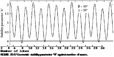 |
We should also be concerned with a local minimum or trough on the geometric stability chart coinciding with an integer number of waves, even if the stability parameter is positive. For example, it can be seen that 18, 20, and 22 waves in Figure 19.46 have troughs on the stability chart. While
![]()
|
Number of waves n FIGURE 19.48 Geometric stability. в = 10° and y = 20°. |
these numbers of waves are stable, large roundness errors will result if a forcing frequency is allowed to excite these values of waviness.
For the above reasons, geometric stability should be tested for integer-wave values as shown in Figure 19.48. This shows that 16 waves is the only geometric instability up to n = 32.
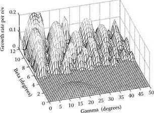
Negative values of A define growth rate as shown in Figure 19.49 for a range of в and у values. Here the unstable zones are shown for n = 3 to 30 waves. For a tangent angle less than 5°, there is only one area of instability and that is for five lobes having low growth rate. Most of the region is stable. However, a tangent angle less than 5° does not provide a rapid rounding action. Therefore, the tangent angle is usually made larger.
There is a small region at в = 7.5°and у = 30° that is stable over the whole range up to n = 32. However, 24 and 26 lobes are only just stable as shown by Figure 19.50. The user can easily construct a range of charts such as Figure 19.50 using a spreadsheet.
In Figure 19.50, n = 24 is only just stable. This may be compared with Figure 19.48 where there is already an instability at n = 16. The stability indicated in Figure 19.50 is, therefore, more favorable on two counts. There is no absolute instability in Figure 19.50 at an integer number of waves. Also, the first marginal instability is at a higher frequency. This is an advantage because higher frequencies reduce the maximum amplitude of waviness due to interference. This point was explained in Section 19.11.6 with reference to simulation of the process. Some authors refer to the
|
|
FIGURE 19.50 Geometric stability for 0 = 7.5° and у = 30.
interference effect as contact filtering. As explained later, there is also a need to consider workpiece speed in relation to dynamic instability. It will be found that if the first marginal geometric instability occurs at a higher number of waves, a higher workpiece speed may be safely employed.

