
 |
 |
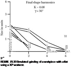
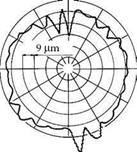
All roundness problems predicted by simulation were experienced in practice when grinding a workpiece with a flat and sometimes when grinding an initially circular workpiece. The simulation technique was tested by comparison with an experimental shape measured after grinding. The pregrinding shape of the workpiece with a flat is shown in Figure 19.40. The workpiece was then ground to the depth of the flat. That is, the radial stock removed was 57 |jm. The postgrinding shape is shown in Figure 19.41.
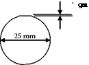 |
FIGURE 19.40 The initial workpiece shape used for experimental determination of rounding effect.
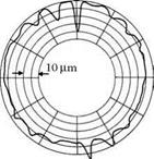
The shape predicted by simulation is shown in Figure 19.41. Agreement with the experimental shape is excellent considering the duration of the grinding cycle over 50 workpiece revolutions. An interesting aspect of the simulation was that it confirmed that the particular grinding setup represented a very compliant system with K = 0.08. This means the depth of cut at any instant was less than 10% of the deflections.
Good correlation between theory and experiment is obtained when the initial workpiece irregularity is large, so that the effect of initial shape predominates over other effects. Usually, grinding results, when magnified to a high degree, exhibit an almost random spread of shapes and magnitudes reflecting the variety of pregrinding shapes and the buildup of errors on the grinding wheel and control wheel. The advantage of working with a large initial roundness error is that it allows the systematic rounding effect to be clearly seen (Figure 19.5 and Figure 19.42).
Starting with a round workpiece, it might be expected that a perfectly round workpiece should result. Simulation shows that this is not necessarily so. Even with a uniform infeed motion and careful sparking-out, small errors result due to the geometry of the rounding action. With a compliant system and optimum setup of the rounding geometry, errors due to infeed motion are extremely small. Typically, the magnitude of the roundness errors due to the infeed motion was less than two thousandths of the magnitude of the infeed per revolution. This means, for example, that if the depth of cut were 10 |jm, the roundness error would typically be 0.01 |jm. In other words the effect is negligible compared with typical roundness errors ranging in precision grinding from 0.2 to 1.0 |jm.
In practice, the best roundness depends on a number of factors including machine vibrations, bearing precision, dressing precision, and wheel wear as outlined in the discussion of the system in Section 19.2.6.
All the roundness problems predicted by simulation were experienced in practice when grinding a workpiece with a flat and sometimes when grinding an initially circular workpiece.
 |
 |
Experimental: Theoretical:
FIGURE 19.41 Experiment compared with simulation./= 20°, в = 8°, K = 0.08. Initial shape: workpiece with flat.